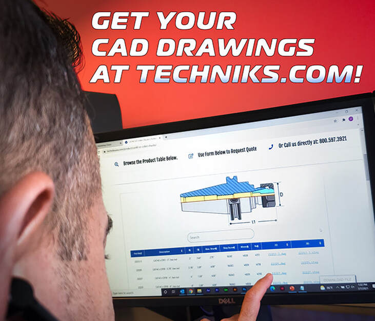
 Techniks is excited to announce that they have compiled 2D and 3D model files for each product available on www.techniksusa.com. That’s almost 4,800 total SKUs, 9,600 2D and 3D model drawings added for your convenience! The addition of downloadable CAD files is just the next phase in our continued development of our site to improve its user-friendliness. You can now find your specific drawings through directly searching for the part number in the “Drawings” section of the main menu or by navigating directly to the product page. Simply navigate to the appropriate product table, locate the item you need, and click on the drawing file format you require. You will see a links to the 2D DWG and 3D STP files in the right-hand columns. Option 1: DOwnload from the tab Just click on the DRAWINGS tab in the top navigation on the website Option 2: Download from the Item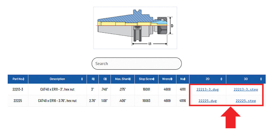 You can just click on the .dwg or .step file to begin the download right from the product page. Option 3: Download from Search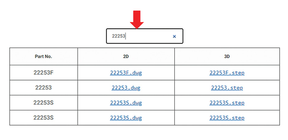 If you have the toolholder or packaging in hand, just type the EDP/ SKU/PART NUMBER in the search bar and you can download it from the results page. Can’t find what you’re looking for?
Techniks is adding more drawings every day, but if you do not find the drawings you need let them know at [email protected] and they'll prioritize your request to get you the drawings you need, FAST! As you begin to take advantage of their available CAD files, please don't hesitate to continue to provide feedback on your website experience. It’s been with your help that Techniks is able to provide the highest levels of customer service.
0 Comments
Decatur Diamond CVD coated diamond tools are a perfect match for machining glass fiber composites. The very abrasive characteristics of composite materials severely limit the life of both carbide and PCD diamond tools.  Decatur Diamond carries a large variety of high performance cutting tools optimized for machining composite materials such as carbon fiber reinforced polymer (CFRP), glass fiber reinforced polymer (GFRP), and metal matrix composites (MMC). Tools with diamond on the surface wear longer and have a lower coefficient of friction. These characteristics provide substantial benefit to machining operations. Because CVD diamond tools last 10-50 times longer than carbide tools, and 3-4 times PCD diamond tools they:
The low friction of CVD diamond tools permit using speeds higher than both carbide and PCD – again contributing to higher productivity – with no degradation of the surface quality or tool life. The consistently sharp edge and lower friction allows delicate, thin wall sections to be machined quickly and precisely. The sharp and long wearing edge also puts lower stresses on the part, fixturing, and equipment. Since CVD diamond has no cobalt binder to break down or abrade away they offer the longest possible tool life. Glass fiber composites can be machined successfully with diamond coated endmills if resin melting and chip evacuation are carefully controlled. Observance of the following guidelines should yield tool lifetimes of approximately 10 times the equivalent carbide tool. Resin MeltingSpeeds and feeds must be adjusted to avoid melting or softening the resin in composite materials. This means that feeds must be 0.001” ipt or greater with larger diameters and speeds should be kept at 400-500 sfm for G10 or FR4 type materials. As the depth of cut increases the cutting speeds should be reduced to below 400 to minimize heat buildup in the chips. For shallow depths of cut, feeds can be up to 0.010” ipt for 1/2” diameter tools. Maximum feed rates are a function of the depth of cut and limited by the tool strength for a given diameter. Chip evacuationFor slot depths exceeding more than 1/2 the diameter of the endmill the evacuations of chips from the slot becomes extremely important. Failure to adequately remove chips can cause breakage of the carbide under the diamond film on the flute edge and subsequent catastrophic failure of the tool. The use of 2-flute tools and moderate-to-high feed rates is highly recommended to insure good chip flow. Air flow into the cut and vacuum evacuation of chips from the cutting area are also recommended. Additional life improvements can be obtained by using a corner radius or ball end tool for the initial cut and then following up with a square end tool with a much shallower cut to achieve the final dimensions. For side cutting applications there is also an issue with chip evacuation if the radial depth of cut exceeds 1/4 of the tool diameter for a 4-flute tool or 2/3 the diameter for a 3-flute tool. Maximum tool life and production rates are generally achieved with 2-flute tools operated at high feed rates for most side cutting applications. Machining Parameters: recommended parameters for sidecutting are listed in the following chart for various flute configurations. Recommendations are based on a cutting speed of 400- 500 sfm and a diameter of the tool greater than or equal to the material thickness. Larger radial depth of cuts are possible if the material is substantially thinner than the tool diameter. 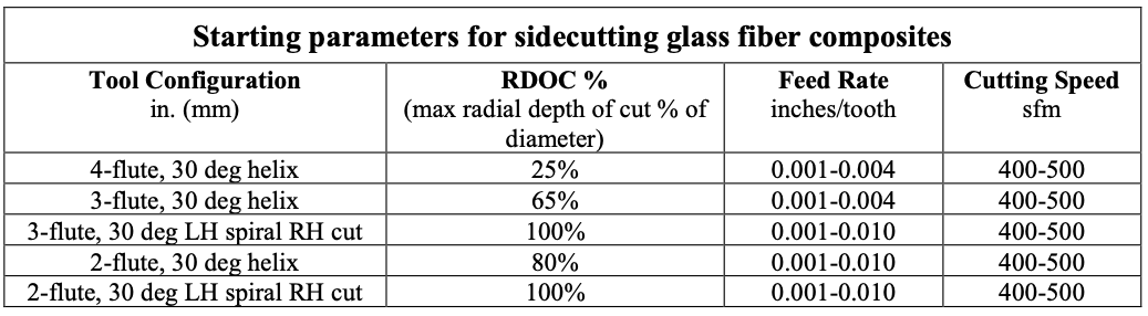 Machining Parameters: recommended parameters for slotting are listed in the following chart for various flute configurations. Recommendations are based on a cutting speed of 400-500 sfm and a full width slot which does not penetrate the full thickness of the material thickness. See sidecutting chart for slots which penetrate the full material thickness. 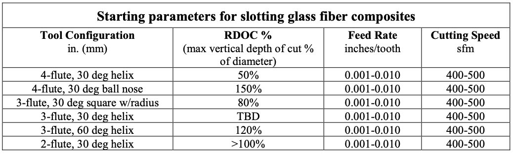 Note: VDOC’s greater than 100% of the tool diameter are listed for informational purposes only and are not recommended for normal operation Decatur Diamond carries a large variety of high performance cutting tools optimized for machining composite materials such as carbon fiber reinforced polymer (CFRP), glass fiber reinforced polymer (GFRP), and metal matrix composites (MMC).
Decatur Diamond products provide the opportunity to machine large parts while minimizing tooling changeovers and ultimately reducing your costs. They can tailor our super hard materials for the challenges at hand with coated CVD, CVD and PCD fabricated tools. Contact us with quesitons!  Decatur Diamond has a complete line of precision cutting tools specifically designed for machining graphite. The tool geometries are optimized for such applications as electrodes, molds, and hydrogen fuel cells. These designs provide excellent cutting performance while not sacrificing tool life. Fewer changeovers and more time in the cut promote long runs and application automation for improved cost savings. CVD coated diamond tools are a perfect match for machining the graphite moldforms for EDM. The abrasive nature of EDM graphite grades severely limit the life of carbide tools, and PCD diamond tools are not available in the configurations required for detailed moldmaking. Tools with diamond on the surface wear longer and have a lower coefficient of friction. These characteristics provide substantial benefit to machining operations. Because diamond tools last 10 to 50 times longer than carbide tools, they:
When cutting graphite, most tool wear is caused by the abrasive nature of the graphite structure rather than by the material temperature or cutting speed. Unlike metal cutting, there is no heat generated when machining graphite, so tool speed is typically not seen as a wear factor. This distinction warrants the need for an abrasion resistant tool surface such as CVD diamond. Because small feeds and depths of cut do not lead to increasing the amount of material chipping, tool wear will advance rapidly with light feed, but stabilize as feed is increased. Therefore, in addition to increasing the volume of material removed, increasing feed can extend tool life. The depth of cut should not exceed one-half of an insert’s leg length or one-third of an endmill’s diameter. These parameters will minimize breakage at the exit of a cut. Tool life is determined by the quality of the cutting edge and the thickness of the diamond layer at the cutting edge. A tool will go through a break in period that refines the cutting edge, resulting in an improved surface finish. This will be followed by a prolonged period of consistent performance and a gradual wearing of the diamond layer. End-of-life occurs when the diamond wears through, revealing the carbide substrate or when the diamond surface becomes chipped or fractured. 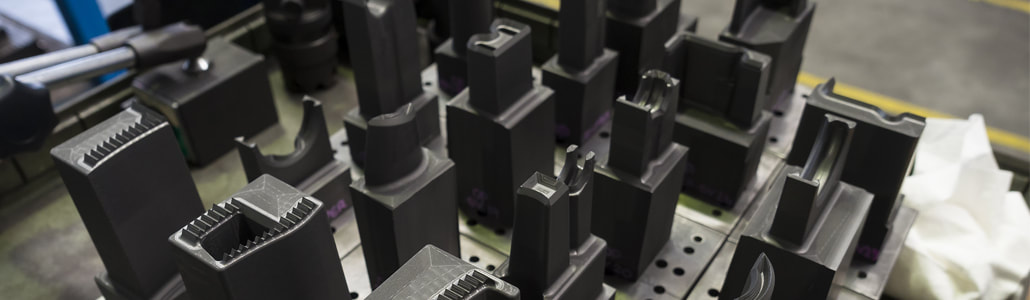 Endmilling Tool configuration: use square endmills with a small radius whenever possible. Diamond tools are more brittle than carbide tools and sharp corners may break upon entry into a cut at high feed rates. A radius of 0.010” to 0.015” will greatly strengthen the tool, providing extra durability. For roughing at high feed rates 2-flute endmills should be used to minimize the possibility of tool breakage from flute packing. For general purpose and finish cutting use 4 flutes. Improved surface finish and longer life usually result from multiple flutes in finishing operations. Chipping: to avoid chipping, several techniques can be employed. Milling a short distance at the exit side of the part before starting the cut is very effective in avoiding breakout, just as chamfering the end of a cylinder is for turning. Lowering feed rates will lessen chipping upon exit, but directly affects productivity. Tool rotation can be used to lessen exit edge chipping for flat surfaces by using climb milling rotation rather than conventional milling rotation. Feed rate: it is important to keep the tool engaged in the cut. If the feed rates drop too low (<.0001 to .0005” or <.00025 to .013mm) the tool tends to burnish the part, rather than cut. This can cause rapid tool wear. When calculating the correct RPM for chip load at a given traverse speed it is important to consider if the machine is ever reaching the optimum traverse speed. It can take 1⁄2” or more to reach a high traverse speed. If the tool path has a lot of small adjustments, reduce RPM’s as the tool is never reaching the full traverse speed. Machining Parameters: starting conditions vary considerably; 2000 SFM and 0.004” per flute per revolution is a conservative start point for 1⁄4” and larger endmills. 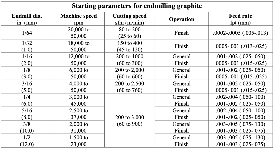 Drilling Dust removal: particular care should be used to clear the machining dust from holes during drilling. Proper removal will allow using higher spindle speed as well as reducing drill wear. Machining Parameters: the table below shows starting machining parameters for drilling graphite. As are all applications, these conditions will vary according to the grade of the graphite being machined and the set-up and dust removal practices. 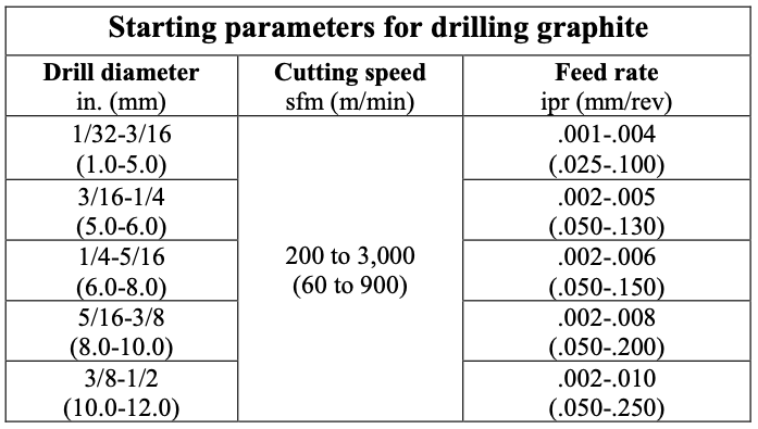 Profiling Machining Parameters: the table below shows starting machining parameters for Dapra & Millstar style ball nose, flat bottom, and back draft profiling cutters. 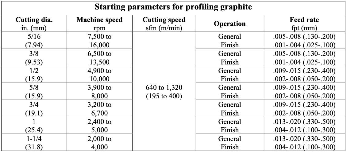 Turning and milling with inserted cutters Tool configuration: perishable inserts with 1/64” to 1/32” nose radii are most effectively used for turning and milling graphite. A positive rake insert with a finish ground flank is preferred. Surface finish: finish can be improved be selecting the appropriate tool geometry and feed rates. Larger nose radii will improve finish, but with increased tool pressure. A smaller nose radius will relieve pressure, but feed must be reduced to achieve comparable surface finish. DOC will not affect surface finish unless it causes excess tool pressure resulting in vibration, or if it is too light (under 0.005”) to remove an adequate amount of material. Breakout: breakout at the end of a pass is always a concern. This can be avoided by having a chamfer cut on the end of the part to ease exit of the tool or provide stock which can be later cut off. Avoid square-nosed cut-off tools to prevent breaking prior to completion of the cut. A 20- degree angle is recommended. Turning Workpiece configuration: when machining long rods and cylinders, higher speeds and depths of cut can be employed with higher strength graphite materials. Depth of cut: DOC should always be maximized when possible without incurring distortion of the part. When distortion is present, feed and DOC must be adjusted. Lower feed rates will allow holding deeper cuts. Feed rates of 0.005” per revolution for roughing and between 0.001” to 0.003”: for finishing might be necessary. Deeper cuts always generate higher pressures and larger fracturing particles, thereby producing rougher surface finishes. Machining Parameters: the table below shows starting machining parameters for general purpose and finish turning. 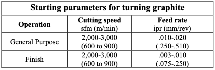 Milling Workpiece configuration: when milling large surfaces or volumes, higher speeds and depths of cut can be employed. Use higher strength graphite materials when there are thin walls involved. Depth of cut: DOC should always be maximized when possible, to reduce multiple passes. Lower feed rates will allow holding deeper cuts. Feed rates of 0.004”/tooth/revolution for roughing and between 0.0005” to 0.002”/tooth/revolution for finishing might be necessary. Multiple cutters: for multiple-pocket milling cutters it is recommended that axial alignment be used to align all inserts within +/-0.0002” for best results. This will improve surface finish and reduce insert wear, as all the inserts will be cutting equally. Machining Parameters: the table below shows starting machining parameters for general purpose and finish turning. 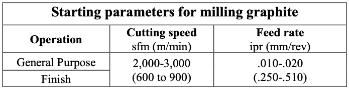 Double Tracking means that the knurling wheels are not tracking properly. In this situation, the knurling wheels will create a different pattern than the original design and may overlap or "double die"
There are two main causes of a knurling tool double tracking:
Dorian Tool has developed a “Knurling Calculator Spreadsheet” that can calculate all of the parameters to avoid double tracking. If you would like to request an electronic copy send us a note in the comments section below or, for faster results, in the form you get when you click the button below. We'll quickly get a spreadsheet sent over to you! Hannibal Carbide has assembled a very nice overview of some common problems associated with carbide reamers and how to avoid them. 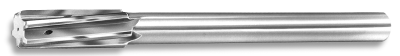 Hannibal Carbide Coolant Fed Reamer Improper Tool
Make sure you are using the correct flute style and tool type. Stock Removal HANNIBAL recommends 2-3% of the reamer diameter as a starting point for stock removal. 2% for steels and tough alloys, 3% for non-ferrous materials and cast irons. Solid carbide & carbide tipped reamers must have adequate stock to remove or they will rub in the hole and generate excessive heat, which leads to premature tool wear. Improper Speeds & Feeds The right combination of speeds and feeds is critical to tool life and consistent size and finish. Getting the correct starting points is a key element. Reaming is a finishing operation and proper speeds and feeds must be run to achieve size, straightness and finish. Poor Fixturing If the fixturing cannot hold the piece securely and in line with the spindle, then producing a good finish will be very difficult. A reamed hole is only going to be as good as the machine and fixturing used to machine and hold the part. Excessing Runout (spindle or tool holder) Runout leads to poor finishes, oversized, tapered, and bellmouth holes, as well as poor tool life. Floating holders or bushings can sometimes be used to compensate for runout, but the best solution is to fix the problem. Improper Coolant Make sure the coolant you are using is recommended for reaming your particular materials. Many coolants will prove effective for reaming if the concentration level is maintained with specifications. Take the time to check the levels on a regular basis. Improper Sharpening or Geometry If a new tool works fine, but fails to perform after resharpening, the problem is obvious. However, depending on the hardness and condition of the material you are reaming, the tool geometry may need to be altered to get optimum performance and tool life. Geometries most often changed are the circular margins, radial rake, and the primary chamfer clearance. Material Changes (hardness and/or condition) Castings lead the way in inconsistency. Hard spots, free carbides, and scale can all lead to inconsistent results when reaming. A heat treatment that varies just a few points from part to part can cause problems. 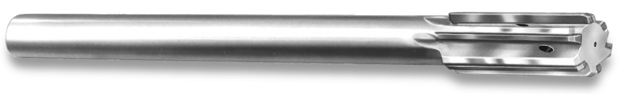 Hannibal Carbide has assembled some basic technical guidelines for optimizing reamers. Following these guidelines will increase your productivity. Ream it right the first time with Hannibal Carbide. Most reamer manufacturers will provide you with a starting point for speeds and feeds. Here's some things to keep in mind:
As you seek the optimum speed and feed for your application, look and listen for signs or sounds that could save you time. Listen for the reamer squealing upon entry—this means speed or feed is too high or alignment is poor. Examine the chip for size and color. Examine the finish for signs of chatter. Here's a short guide on understanding Cut Tap Chamfers. This is an excerpt from Allen Benjamin's Technical Tap Guide Engineering Data. 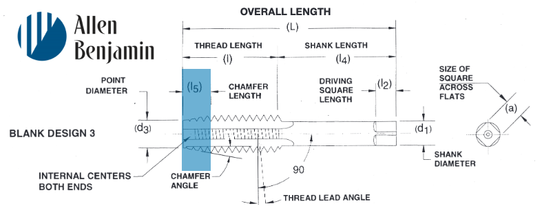 A tap chamfer is the tapering of the threads to distribute cutting action over several teeth. The type of hole to be tapped has much to do with the chamfer style of that tap that’s best suited. Some holes go all the way through. Some, while not through-holes, are relatively deep. Some are quite shallow (a little deeper than diameter). Each of these three kinds of holes - through, deep-bottoming blind, and shallow bottoming - has a tap chamfer best suited to specific threading requirements. 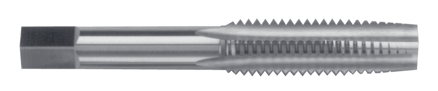 Allen Benjamin Taper Tap Taper Taps This style, with a 7-10 thread chamfer, has the longest chamfer of the three to distribute action over the maximum number of teeth; and the taper also acts as a guide in starting the cutting action in the hole. Taper style taps start the thread square with the workpiece. Taper taps are commonly used in through holes and in materials where a tapered guide is necessary. 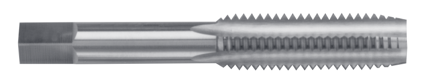 Allen Benjamin Plug Tap Plug Taps This style, with a 3-5 thread chamfer, is most widely used in through holes and where there is sufficient room at the bottom in blind holes. Semi (or Modified) Bottoming Taps This style, with a 2 to 2.5 thread chamfer, should be used when-ever possible in difficult material applications in blind holes, when threads are not required to the bottom of the hole 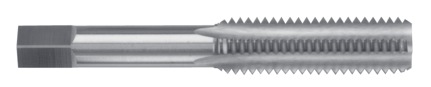 Allen Benjamin Bottoming Tap Bottoming Style This style, designed with a 1 to 2 thread chamfer, is made with just enough chamfer for starting in the hole; as the name implies, it is designed to thread blind holes to the bottom. PLEASE NOTE: Taper, plug and bottoming taps as a set, in a given size (for example: 1/4-20 NC) are identical as to size, length and vi-tal measurements; the difference is in the chamfered threaded portion at the point. As a rule, such taps when used by hand are furnished in sets of three of a given size...namely, taper, plug and bottoming (and should be used in that order)
Tech Tips: Dorian Tool Installing a turret can give a real productivity boost for shops. With a CNC turret, more tools can be carried at one time. 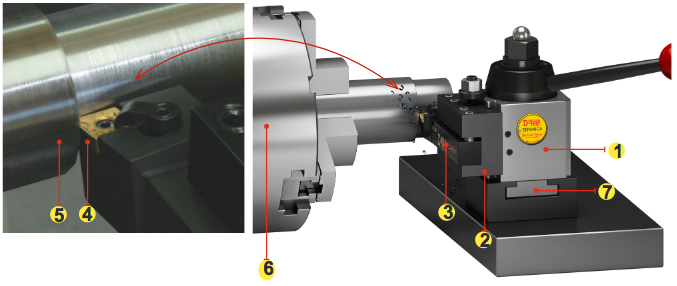 Turning Application with a Manual or CNC Toolroom Lathe 1.Quick Change Tool Post 2.Quick Change Turning and Facing Toolholder 3.Square Shank Toolholder 4.Insert 5.Workpiece 6.Chuck 7.Custom T-Nut The lathe is one of the oldest and most versatile machine tools. Few shops can do without the processing capability offered by the CNC lathe. Long before automatic toolchangers were applied to milling machines, the lathe had a multiple-tool configuration. The tool post gave lathe users the ability to select from several mounted tools and index them as needed during a turning cycle. Many CNC lathes are still offered with the manual tool post design. Shops can generally purchase these machines at very reasonable prices. Some shops have found a need to increase the flexibility of these lathes by adding an indexable turret in place of the manual tool post. 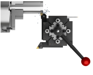 Installing such a turret can give a real productivity boost for shops running on Colchester, Harrison, Nardini, Bridgeport, Southwest Industries and other popular combination CNC lathes. With a CNC turret, more tools can be carried at one time. Programming the turret brings the right tool into the cut at the right time automatically. No stopping the machine to index a manually operated tool post is needed so cycle times are reduced for applications that use more than one tool. For many turning applications a manual tool post has sufficient capacity. But any shop that is looking for a through-put gain in their turning operation without a major investment in new machine tools, can benefit by considering installation of a CNC turret. The issue is more about processing efficiency than tool capacity, says lathe accessory maker, Dorian Tool (East Bernard, Texas). A turret configuration allows the machine tool to carry tools mounted in operation sequence. Sometimes turret tool capacity is sufficient for more than one job to run without a tooling setup in between. But significant production time is saved by the ability to automatically index the tool turret as part of the lathe's part processing program. The turret offered by Dorian Tool is a bi-directional unit. Indexing therefore takes the shortest part from one tool station to another. It's operated by a three-phase 220/380 volt 50/60 hertz electric motor through an anti-backlash gear drive. Tool position is controlled by an absolute encoder which tracks actual position of the tool station. The working position of the turret can be right or left hand depending on the unit location ahead of or behind the lathe's spindle axis. A proximity switch detects tool position and verifies turret lockup before a go signal is sent to the CNC. A three-piece Hirth-type coupling is used to hold the clamped turret radially. The turret indexes, station-to-station under one second. Fast index is achieved by not lifting the turret face. The entire indexing mechanism is housed in a Meehanite grade casting that helps damp cutting induced vibrations. Four standard sizes of turrets are available. They are 100, 120, 160 and 200 mm respectively. Toolholding capacities of eight or 12 stations are available in ID, OD or combined tooling configurations. Tool capacities range from 12 to 32 mm (1/2 to 1-1/4 inches). A VDI turret disk is available. Both turret disks have an integral coolant delivery system. Simple electrical and coolant connections easily interface with the lathe. If an indexable turret is the difference between a CNC lathe and a CNC turning center, then this accessory is a cost effective way to up-grade your lathes. Tech Tip: Dorian Tool Double Tracking means that the knurling wheels are not tracking properly.
In this situation, the wheels will create a different pattern than what the design was originally made for. There are two main causes of this scenario:
Dorian Tool Developed a “Knurling Calculator Spreadsheet” that can calculate all of the parameters to avoid double tracking. Request an electronic copy by emailing us at: [email protected] Tech Tip: Hannibal Carbide 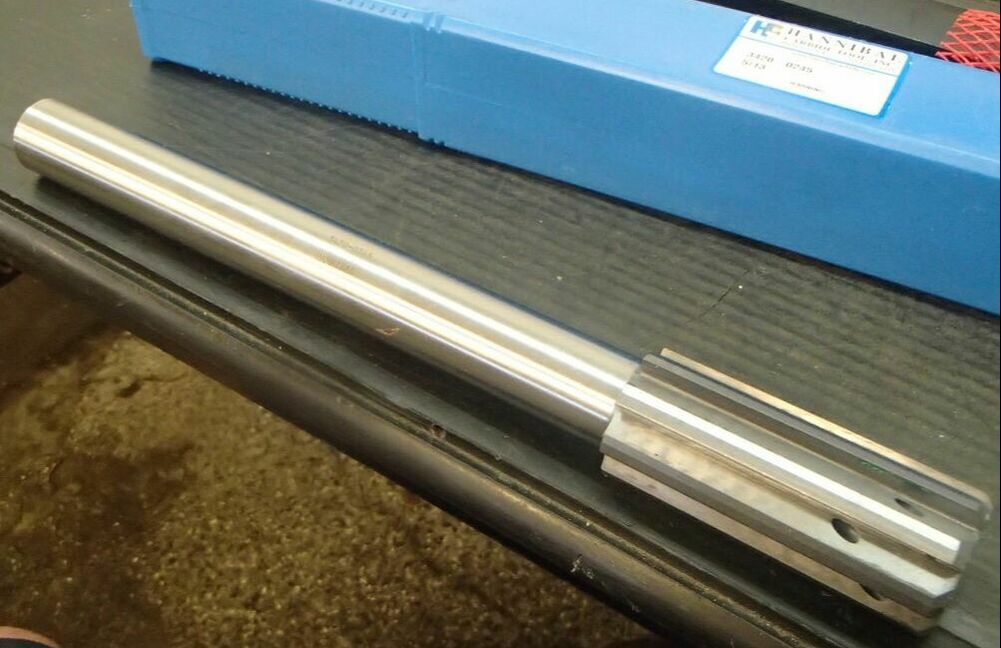 Hannibal Carbide has compiled this guide to inform you of some basic technical knowledge regarding reamers. Following these guidelines will reduce overall set-up time, while increasing productivity. Selecting the right tool, proper stock removal and correct speeds and feeds are all important and covered here in the Hannibal Carbide Reamer Guide. "Ream it right the first time with Hannibal" Flute Styles Straight Flute Best suited for non-chip forming materials, i.e. cast iron, bronze and free cutting brass. Preferred hole condition would be a thru hole. Right Hand Spiral Designed to pull the chip out of the hole in a blind hole application.Due to aggressive flute geometry, a right hand spiral may cut slightly oversized.Effective in bridging interruptions, such as keyways, cross-holes, etc.Excellent in highly ductile materials. Left Hand Spiral Excellent in thru holes, as the flutes tend to push the chips out ahead of the reamer.Effective in bridging interruptions, such as keyways, cross-holes, etc.Good for reaming hard materials.Should provide the very best size and finish. Expansion Reamers Designed for high production runs in abrasive materials, when size or finish can be rapidly lost.Expand the diameter by turning the screw clockwise.The tool is now ready to be reground back to its original diameter and resharpened.This process should produce like new tool performance. Coolant Options Center Fed Coolant (axial) Center fed coolant design is used for blind hole reaming.Combine center fed coolant with right hand spiral for maximum chip clearing ability in highlyductile material. Flute Fed Coolant (radial) Flute fed coolant design is used for thru hole reaming.Effective in a cavity large enough for chip clearance.Flute fed coolant will flush the chips ahead of the reamer, providing the best hole size and finish.  OPTIMUM OPERATING CONDITIONS While developing optimum conditions will require some investment in time, it will be beneficial by reducing cycle times and getting the best possible tool life. There are several elements to evaluate in this section. These elements are key to maximizing tool efficiency
|
ABOUT
This is where we publish technical articles, applications stories, tip and tricks, new product announcements and press releases. Archive
June 2024
Categories
All
|
 RSS Feed
|
|
F&L Technical Sales Inc.
326 Woodland Way Russell, MA 01071 Established 1999
|
© 2024 F&L Technical Sales Inc.
All Rights Reserved site design: Rapid Production Marketing
|