|
by Bernard Martin Unlock the full potential of your composite machining with Decatur Diamond's high-performance cutting tools! From carbon fiber and glass fiber reinforced polymers to metal matrix composites, their extensive range includes versatile routers, honeycomb routers, compression routers, diamond cut routers, and drilling products. Engineered for precision, durability, and efficiency, their tools minimize delamination and fiber pullout while ensuring clean, precise cuts and extended tool life. Discover why Decatur Diamond is the industry leader in advanced tooling solutions for composite materials.  Decatur Diamond offers a broad range of tools for matching composites. Show here from right to left:End mIlls, Compression Router, Honeycomb Router, Diamond Coated Turning Inserts, Router and Drills. Decatur Diamond offers an extensive range of high-performance cutting tools optimized for machining composite materials, including carbon fiber reinforced polymer (CFRP), glass fiber reinforced polymer (GFRP), and metal matrix composites (MMC). These advanced tools allow for the efficient machining of large parts, reducing tooling changeovers and overall costs. By tailoring super hard materials such as coated CVD, CVD, and PCD fabricated tools, Decatur Diamond meets the unique challenges of machining composites. Below is an overview of our specific product lines that make Decatur Diamond's tools unique in the industry.  Decatur Diamond's Diamond Coated End Mills Decatur Diamond's Diamond Coated End Mills Diamond Coated End Mills Decatur Diamond 's Diamond Coated End Mills are designed for high-performance machining of non-ferrous materials. With potentially the best diamond adhesion in the coated tool industry, these tools offer coating thickness and crystal size options to meet various application requirements. Available in square, corner rounding, ball, and profiling geometries, these end mills ensure superior performance and tool life. Sizes start from 0.015” (1mm) and can be customized for special applications.
 Decatur Diamond's Diamond Coated Inserts Decatur Diamond's Diamond Coated Inserts Diamond Coated Inserts Decatur Diamond 's Diamond Coated Inserts are available in common ISO & ANSI standards, as well as in milling insert forms. These inserts come with various coating thickness and crystal size options to meet different application needs, ensuring high performance and durability. Geometries include CCMT, CNMP, DCMT, DNMP, TCMT, TPG, TPGH, VBMT, VBMW, and VNMP styles
 Decatur Diamond’s Versatile Router Decatur Diamond’s Versatile Router Versatile Router Decatur Diamond’s Versatile Router is designed for a wide range of composite materials, providing excellent performance and durability. These routers are particularly effective in minimizing delamination and fiber pullout, ensuring clean and precise cuts. The versatile design allows for adaptability in various applications, reducing the need for multiple tools and streamlining the machining process.  Decatur Diamond’s Honeycomb Router Honeycomb Router Decatur Diamond ’s Honeycomb Router is specifically engineered for machining honeycomb structures, which are common in aerospace and other high-performance industries. These routers are designed to maintain the structural integrity of the honeycomb material while providing smooth and accurate cuts. The unique geometry and cutting edge design minimize fraying and ensure a longer tool life.  Decatur Diamond Compression Router Compression Router The Compression Router from Decatur Diamond is optimized for machining layered composite materials. It features a unique compression design that pushes the material toward the center of the tool, preventing delamination on both the top and bottom surfaces of the workpiece. This tool is ideal for applications requiring high surface finish and precision.  Decatur Diamond's Diamond Cut Router Diamond Cut Router The Decatur Diamond Diamond Cut Router is known for its exceptional cutting capabilities and long tool life. With diamond-coated edges, this router offers superior wear resistance and performance when machining abrasive composite materials. It is perfect for high-volume production environments where tool longevity and consistent performance are critical.  Diamond Coated Drills Diamond Coated Drills Diamond Coated Drills Decatur Diamond offers a comprehensive line of diamond-coated carbide drills designed for non-ferrous and composite material applications. These drills, available in a variety of geometries and coating thickness options, ensure superior performance and extended tool life. The optimized tool geometries ensure superior performance and extended tool life, making them ideal for drilling precise holes in challenging materials. With diameters ranging from 0.028” to 0.750” (1mm to 12.50mm), including most letter, #, and wire sizes, they are ideal for precision drilling in challenging materials.
Decatur Diamond’s commitment to innovation and quality makes our tools the preferred choice for machining composite materials. With tailored solutions and a focus on reducing operational costs, our high-performance tools help you achieve superior results in your machining processes.
0 Comments
 Decatur Diamond has a complete line of precision cutting tools specifically designed for machining graphite. The tool geometries are optimized for such applications as electrodes, molds, and hydrogen fuel cells. These designs provide excellent cutting performance while not sacrificing tool life. Fewer changeovers and more time in the cut promote long runs and application automation for improved cost savings. CVD coated diamond tools are a perfect match for machining the graphite moldforms for EDM. The abrasive nature of EDM graphite grades severely limit the life of carbide tools, and PCD diamond tools are not available in the configurations required for detailed moldmaking. Tools with diamond on the surface wear longer and have a lower coefficient of friction. These characteristics provide substantial benefit to machining operations. Because diamond tools last 10 to 50 times longer than carbide tools, they:
When cutting graphite, most tool wear is caused by the abrasive nature of the graphite structure rather than by the material temperature or cutting speed. Unlike metal cutting, there is no heat generated when machining graphite, so tool speed is typically not seen as a wear factor. This distinction warrants the need for an abrasion resistant tool surface such as CVD diamond. Because small feeds and depths of cut do not lead to increasing the amount of material chipping, tool wear will advance rapidly with light feed, but stabilize as feed is increased. Therefore, in addition to increasing the volume of material removed, increasing feed can extend tool life. The depth of cut should not exceed one-half of an insert’s leg length or one-third of an endmill’s diameter. These parameters will minimize breakage at the exit of a cut. Tool life is determined by the quality of the cutting edge and the thickness of the diamond layer at the cutting edge. A tool will go through a break in period that refines the cutting edge, resulting in an improved surface finish. This will be followed by a prolonged period of consistent performance and a gradual wearing of the diamond layer. End-of-life occurs when the diamond wears through, revealing the carbide substrate or when the diamond surface becomes chipped or fractured. 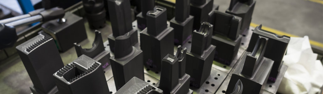 Endmilling Tool configuration: use square endmills with a small radius whenever possible. Diamond tools are more brittle than carbide tools and sharp corners may break upon entry into a cut at high feed rates. A radius of 0.010” to 0.015” will greatly strengthen the tool, providing extra durability. For roughing at high feed rates 2-flute endmills should be used to minimize the possibility of tool breakage from flute packing. For general purpose and finish cutting use 4 flutes. Improved surface finish and longer life usually result from multiple flutes in finishing operations. Chipping: to avoid chipping, several techniques can be employed. Milling a short distance at the exit side of the part before starting the cut is very effective in avoiding breakout, just as chamfering the end of a cylinder is for turning. Lowering feed rates will lessen chipping upon exit, but directly affects productivity. Tool rotation can be used to lessen exit edge chipping for flat surfaces by using climb milling rotation rather than conventional milling rotation. Feed rate: it is important to keep the tool engaged in the cut. If the feed rates drop too low (<.0001 to .0005” or <.00025 to .013mm) the tool tends to burnish the part, rather than cut. This can cause rapid tool wear. When calculating the correct RPM for chip load at a given traverse speed it is important to consider if the machine is ever reaching the optimum traverse speed. It can take 1⁄2” or more to reach a high traverse speed. If the tool path has a lot of small adjustments, reduce RPM’s as the tool is never reaching the full traverse speed. Machining Parameters: starting conditions vary considerably; 2000 SFM and 0.004” per flute per revolution is a conservative start point for 1⁄4” and larger endmills. 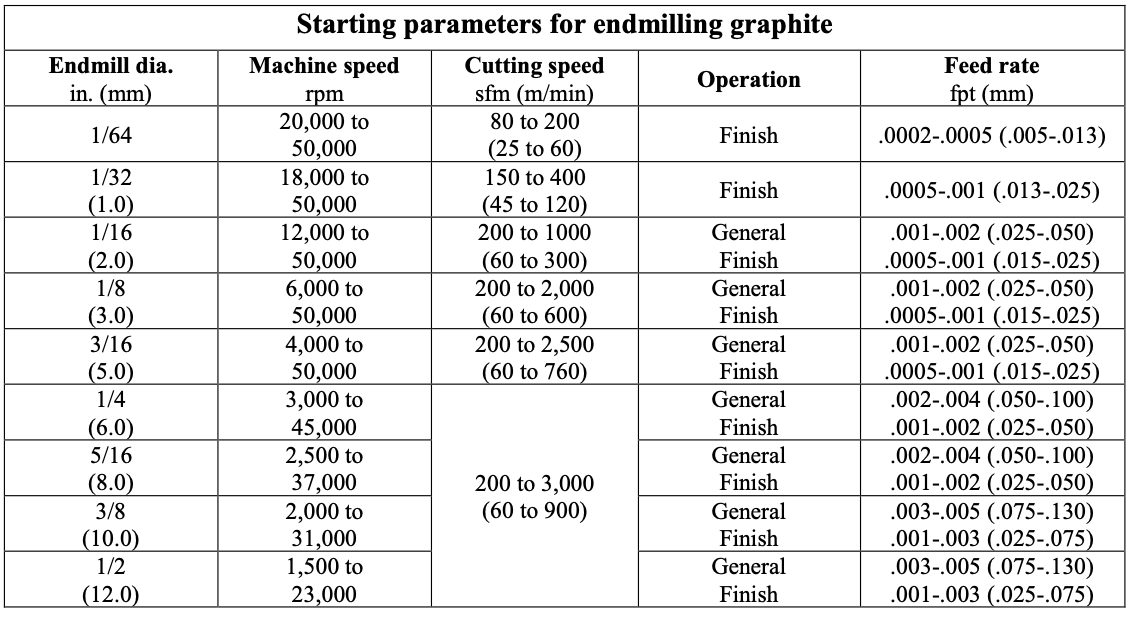 Drilling Dust removal: particular care should be used to clear the machining dust from holes during drilling. Proper removal will allow using higher spindle speed as well as reducing drill wear. Machining Parameters: the table below shows starting machining parameters for drilling graphite. As are all applications, these conditions will vary according to the grade of the graphite being machined and the set-up and dust removal practices. 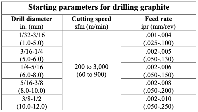 Profiling Machining Parameters: the table below shows starting machining parameters for Dapra & Millstar style ball nose, flat bottom, and back draft profiling cutters. 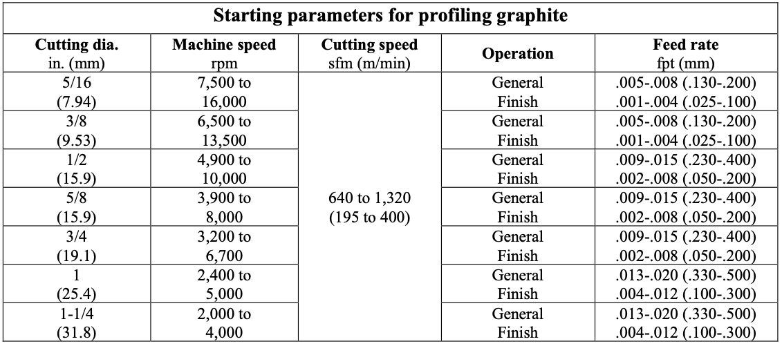 Turning and milling with inserted cutters Tool configuration: perishable inserts with 1/64” to 1/32” nose radii are most effectively used for turning and milling graphite. A positive rake insert with a finish ground flank is preferred. Surface finish: finish can be improved be selecting the appropriate tool geometry and feed rates. Larger nose radii will improve finish, but with increased tool pressure. A smaller nose radius will relieve pressure, but feed must be reduced to achieve comparable surface finish. DOC will not affect surface finish unless it causes excess tool pressure resulting in vibration, or if it is too light (under 0.005”) to remove an adequate amount of material. Breakout: breakout at the end of a pass is always a concern. This can be avoided by having a chamfer cut on the end of the part to ease exit of the tool or provide stock which can be later cut off. Avoid square-nosed cut-off tools to prevent breaking prior to completion of the cut. A 20- degree angle is recommended. Turning Workpiece configuration: when machining long rods and cylinders, higher speeds and depths of cut can be employed with higher strength graphite materials. Depth of cut: DOC should always be maximized when possible without incurring distortion of the part. When distortion is present, feed and DOC must be adjusted. Lower feed rates will allow holding deeper cuts. Feed rates of 0.005” per revolution for roughing and between 0.001” to 0.003”: for finishing might be necessary. Deeper cuts always generate higher pressures and larger fracturing particles, thereby producing rougher surface finishes. Machining Parameters: the table below shows starting machining parameters for general purpose and finish turning. 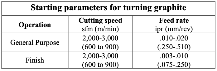 Milling Workpiece configuration: when milling large surfaces or volumes, higher speeds and depths of cut can be employed. Use higher strength graphite materials when there are thin walls involved. Depth of cut: DOC should always be maximized when possible, to reduce multiple passes. Lower feed rates will allow holding deeper cuts. Feed rates of 0.004”/tooth/revolution for roughing and between 0.0005” to 0.002”/tooth/revolution for finishing might be necessary. Multiple cutters: for multiple-pocket milling cutters it is recommended that axial alignment be used to align all inserts within +/-0.0002” for best results. This will improve surface finish and reduce insert wear, as all the inserts will be cutting equally. Machining Parameters: the table below shows starting machining parameters for general purpose and finish turning. 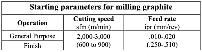 Tech Tips: Decatur Diamond  CVD coated diamond tools are a perfect match for machining carbon fiber composites (CFC) such as carbon fiber reinforced polymer (CFRP). The very abrasive characteristics of composite materials severely limit the life of both carbide and PCD diamond tools. Tools with diamond on the surface wear longer and have a lower coefficient of friction. These characteristics provide substantial benefit to machining operations. Because CVD diamond tools last 10-50 times longer than carbide tools, and 3-4 times PCD diamond tools they:
The low friction of CVD diamond tools permit using speeds higher than both carbide and PCD – again contributing to higher productivity – with no degradation of the surface quality or tool life. The consistently sharp edge and lower friction allows delicate, thin wall sections to be machined quickly and precisely. The sharp and long wearing edge also puts lower stresses on the part, fixturing, and equipment. Since CVD diamond has no cobalt binder to break down or abrade away they offer the longest possible tool life. Carbon fiber composites can be machined successfully with diamond coated endmills if resin melting and chip evacuation are carefully controlled. Observance of the following guidelines should yield tool lifetimes of approximately 10 times the equivalent carbide tool. Resin Melting: Speeds and feeds must be adjusted to avoid melting or softening the resin in composite materials. This means that feeds must be 0.001” ipt or greater with larger diameters and speeds should be kept at 400-500 sfm for most types of materials. As the depth of cut increases the cutting speeds should be reduced to below 400 to minimize heat buildup in the chips. For shallow depths of cut, feeds can be up to 0.010” ipt for 1/2” diameter tools. Maximum feed rates are a function of the depth of cut and limited by the tool strength for a given diameter. Chip Evacuation: For slot depths exceeding more than 1/2 the diameter of the endmill the evacuations of chips from the slot becomes extremely important. Failure to adequately remove chips can cause breakage of the carbide under the diamond film on the flute edge and subsequent catastrophic failure of the tool. The use of 2-flute tools and moderate-to-high feed rates is highly recommended to insure good chip flow. Air flow into the cut and vacuum evacuation of chips from the cutting area are also recommended. Additional life improvements can be obtained by using a corner radius or ball end tool for the initial cut and then following up with a square end tool with a much shallower cut to achieve the final dimensions. For side cutting applications there is also an issue with chip evacuation if the radial depth of cut exceeds 1/4 of the tool diameter for a 4-flute tool or 2/3 the diameter for a 3-flute tool. Maximum tool life and production rates are generally achieved with 2-flute tools operated at high feed rates for most side cutting applications. Sidecutting Machining Parameters: Recommended parameters for sidecutting are listed in the following chart for various flute configurations. Recommendations are based on a cutting speed of 400-500 sfm and a diameter of the tool greater than or equal to the material thickness. Larger radial depth of cuts are possible if the material is substantially thinner than the tool diameter. 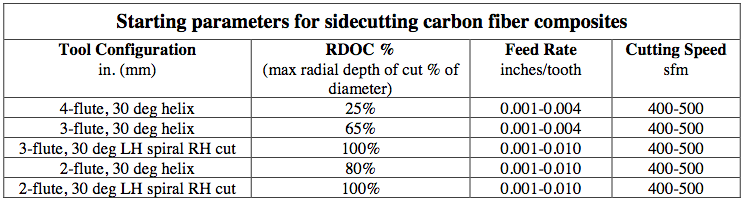 Slotting Machining Parameters: The recommended parameters for slotting are listed in the following chart for various flute configurations. Recommendations are based on a cutting speed of 400-500 sfm and a full width slot which does not penetrate the full thickness of the material thickness. See the sidecutting chart above for slots which penetrate the full material thickness. 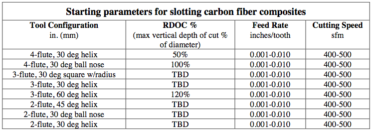 Note: VDOC’s greater than 100% of the tool diameter are listed for informational purposes only and are not recommended for normal operation.
|
ABOUT
This is where we publish technical articles, applications stories, tip and tricks, new product announcements and press releases. Archive
June 2024
Categories
All
|
 RSS Feed
|
|
F&L Technical Sales Inc.
326 Woodland Way Russell, MA 01071 Established 1999
|
© 2024 F&L Technical Sales Inc.
All Rights Reserved site design: Rapid Production Marketing
|