|
Tech Tips: Decatur Diamond  CVD coated diamond tools are a perfect match for machining carbon fiber composites (CFC) such as carbon fiber reinforced polymer (CFRP). The very abrasive characteristics of composite materials severely limit the life of both carbide and PCD diamond tools. Tools with diamond on the surface wear longer and have a lower coefficient of friction. These characteristics provide substantial benefit to machining operations. Because CVD diamond tools last 10-50 times longer than carbide tools, and 3-4 times PCD diamond tools they:
The low friction of CVD diamond tools permit using speeds higher than both carbide and PCD – again contributing to higher productivity – with no degradation of the surface quality or tool life. The consistently sharp edge and lower friction allows delicate, thin wall sections to be machined quickly and precisely. The sharp and long wearing edge also puts lower stresses on the part, fixturing, and equipment. Since CVD diamond has no cobalt binder to break down or abrade away they offer the longest possible tool life. Carbon fiber composites can be machined successfully with diamond coated endmills if resin melting and chip evacuation are carefully controlled. Observance of the following guidelines should yield tool lifetimes of approximately 10 times the equivalent carbide tool. Resin Melting: Speeds and feeds must be adjusted to avoid melting or softening the resin in composite materials. This means that feeds must be 0.001” ipt or greater with larger diameters and speeds should be kept at 400-500 sfm for most types of materials. As the depth of cut increases the cutting speeds should be reduced to below 400 to minimize heat buildup in the chips. For shallow depths of cut, feeds can be up to 0.010” ipt for 1/2” diameter tools. Maximum feed rates are a function of the depth of cut and limited by the tool strength for a given diameter. Chip Evacuation: For slot depths exceeding more than 1/2 the diameter of the endmill the evacuations of chips from the slot becomes extremely important. Failure to adequately remove chips can cause breakage of the carbide under the diamond film on the flute edge and subsequent catastrophic failure of the tool. The use of 2-flute tools and moderate-to-high feed rates is highly recommended to insure good chip flow. Air flow into the cut and vacuum evacuation of chips from the cutting area are also recommended. Additional life improvements can be obtained by using a corner radius or ball end tool for the initial cut and then following up with a square end tool with a much shallower cut to achieve the final dimensions. For side cutting applications there is also an issue with chip evacuation if the radial depth of cut exceeds 1/4 of the tool diameter for a 4-flute tool or 2/3 the diameter for a 3-flute tool. Maximum tool life and production rates are generally achieved with 2-flute tools operated at high feed rates for most side cutting applications. Sidecutting Machining Parameters: Recommended parameters for sidecutting are listed in the following chart for various flute configurations. Recommendations are based on a cutting speed of 400-500 sfm and a diameter of the tool greater than or equal to the material thickness. Larger radial depth of cuts are possible if the material is substantially thinner than the tool diameter. 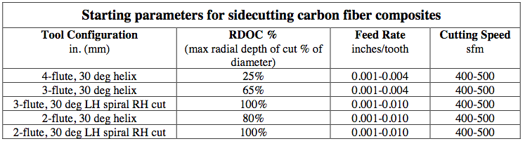 Slotting Machining Parameters: The recommended parameters for slotting are listed in the following chart for various flute configurations. Recommendations are based on a cutting speed of 400-500 sfm and a full width slot which does not penetrate the full thickness of the material thickness. See the sidecutting chart above for slots which penetrate the full material thickness. 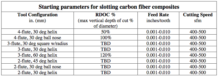 Note: VDOC’s greater than 100% of the tool diameter are listed for informational purposes only and are not recommended for normal operation.
10 Comments
Tech Tips: Hannibal Carbide If you are ordering a special drill, here is the nomenclature you should be familiar with when preparing to write your specifications.  Modern CNC machines feature high-capacity tool changers that automatically swap toolholders in and out of the spindle as needed, by means of a high speed swing arm or a rotary carousel. Periodically, toolholders should be examined for wear and if necessary replaced to maintain cutting performance. New operators should be taught how to properly evaluate toolholders so they can recognize when toolholders need to be replaced to prevent premature cutting tool failure, or even expensive damage to the spindle. 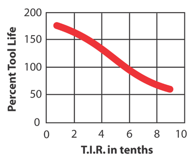 You lose 10% of cutting tool life for every “tenth” (0.0001”) of runout You lose 10% of cutting tool life for every “tenth” (0.0001”) of runout Many operators do not know why it is necessary to replace their tooling, or have the experience to tell when it is time to do so. Determining if toolholder components need to be replaced is not a difficult task, but does require that the operator knows what to look for. A worn out holder will not provide good accuracy and will quickly wear out your cutting tools. Worn tooling causes poor surface finish, and may damage your spindle. This article will discuss the following types of causes and types of wear.
Checking For Spindle Mouth Wear A worn spindle can cause runout issues that affect tool-holder accuracy and reduce cutting quality and productivity. This is a condition known as bell mouthing. If toolholder issues can be eliminated by bench checking T.I.R., then the source of the problem is often a worn out spindle mouth. A trained professional will be required to check and repair bell mouthing. 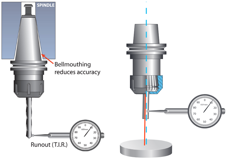 T.I.R. (total indicator runout) is the measurement of axial deflection of the cutting tool in the toolholder assembly. Techniks toolholders are manufactured to minimize runout and extend cutting tool life.
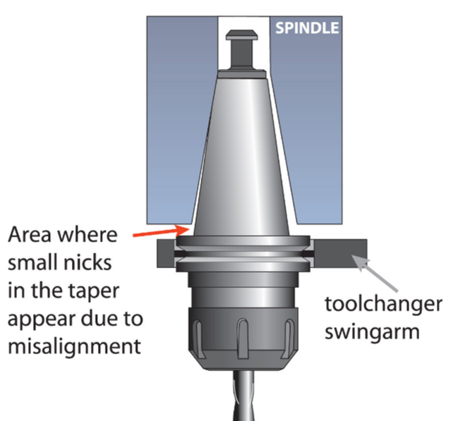
Taper Wear / Fretting Check the taper for signs of wear or damage where it contacts the spindle mouth. Any problems with the taper will have a direct effect on machining accuracy. If there are any imperfections on the taper, the toolholder should not be used. If noticeable marking is evident on the taper a condition called fretting may be occurring. Fretting happens when two steel parts (holder and spindle mouth) are rubbing against one another. Once a toolholder is fretted it can pass the fretting to other spindles. A spindle with fretting can pass the fretting to other toolholders. Fretting in this sense if akin to sexually transmitted diseases and it should be considered just a seriously. 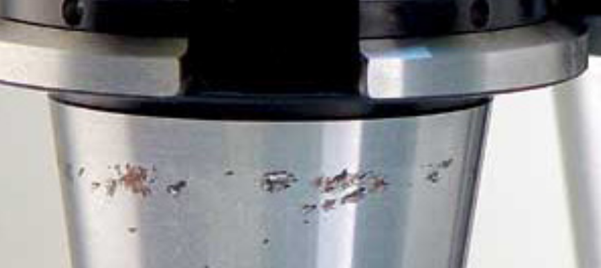 Fretting is evident from the bronze discoloration on the toolholder taper. It will also be present on the spindle. It can spread to other toolholders. Fretting is believed to be caused by imperfect mating between tooholder taper and spindle, creating vibration and heat which develops the fretting. It is visible as small copper colored pits or marks on the taper. This is evidence that the toolholder is becoming worn. Fret-ting is easily mistaken for rust, but it is not. Once noticeable fretting develops the toolholder should be replaced. New toolholders that quickly develop fretting, or toolholders that stick in the spindle, may indicate a spindle that needs to be reground.
|
ABOUT
This is where we publish technical articles, applications stories, tip and tricks, new product announcements and press releases. Archive
March 2024
Categories
All
|
 RSS Feed
|
|
F&L Technical Sales Inc.
326 Woodland Way Russell, MA 01071 Established 1999
|
© 2024 F&L Technical Sales Inc.
All Rights Reserved site design: Rapid Production Marketing
|