|
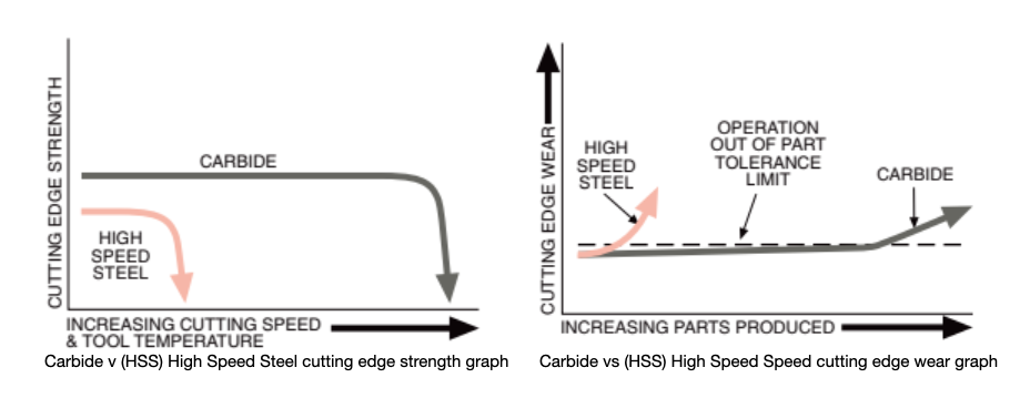
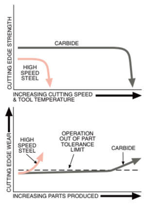
compiled and edited by Bernard Martin The choice between various materials can significantly impact performance, productivity, and cost-effectiveness in Metalcutting manufacturing. Among the materials commonly used for cutting tools, carbide-tipped tools have remained in prominence for their remarkable advantages when compared to solid carbide and high-speed steel (HSS) tools. In this article, based upon information supplied by Hannibal Carbide, we explore the distinctive benefits of carbide-tipped tools by comparing them to their solid carbide and HSS counterparts. Durability and Longevity One of the foremost advantages of carbide-tipped tools is their exceptional durability and longevity. These tools combine the best of both worlds, featuring a tough steel body with a carbide insert at the cutting edge. When compared to solid carbide tools, carbide-tipped tools often outlast them due to their ability to withstand high-impact applications. In contrast, HSS tools are more prone to wear and require frequent regrinding or replacement Versatility Carbide-tipped tools offer a remarkable level of versatility. The carbide inserts are available in various grades, each tailored to specific machining tasks. This adaptability allows users to choose the ideal carbide grade for their application, optimizing tool life and performance. In contrast, solid carbide tools, while highly capable in specific applications, lack the flexibility to adapt to various materials and machining conditions. HSS tools, though versatile, may not match the cutting speed and precision of carbide-tipped tools in demanding applications. Cutting Speed and Efficiency Carbide-tipped tools excel in cutting speed and efficiency, making them a preferred choice for high-production environments. The hardness of carbide allows for faster cutting speeds, which translates to reduced machining time and increased productivity. Solid carbide tools come close but may not always match the speed and efficiency of carbide-tipped tools, especially when it comes to demanding materials like stainless steel or hardened alloys. HSS tools, on the other hand, are often outpaced in terms of cutting speed and efficiency. Heat Resistance Heat resistance is a critical factor in machining, especially when working with materials that generate high temperatures during cutting. Carbide-tipped tools have superior heat resistance compared to HSS tools. The carbide can endure high temperatures without losing its cutting edge, ensuring consistent performance even under demanding conditions. Solid carbide tools have good heat resistance but may be prone to chipping or breakage when subjected to extreme heat, which is less of an issue for carbide-tipped tools. Cost-Effectiveness While the initial cost of carbide-tipped tools may be higher than HSS tools, their durability and longevity make them a cost-effective choice in the long run. Solid carbide tools, while durable, can be more expensive and may not justify their cost in all applications. HSS tools, although cheaper initially, may need more frequent replacements and regrinding, ultimately incurring higher costs over time. In the world of cutting tools, carbide-tipped tools stand out as a versatile, high-performance, and cost-effective solution. Their unique combination of a tough steel body with a carbide insert at the cutting edge offers durability, versatility, high cutting speeds, heat resistance, and cost savings. While solid carbide and high-speed steel tools have their merits in specific applications, carbide-tipped tools are the go-to choice for industries and machinists looking to maximize efficiency and quality across a wide range of machining tasks. Whether you're working with metals, plastics, or composites, carbide-tipped tools provide a winning edge in the world of precision cutting and machining. Advantages of Carbide Tipped |
|
Advantages of CARBIDE TIPPED
VS.
SOLID CARBIDE ADVANTAGE
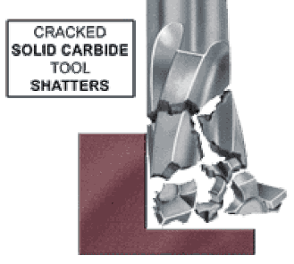 Cracked solid carbide tool shatters
 - Carbide grade selected for cutting characteristics - not compromised for structural strength
- Tipped tools usually cost less than solid carbide
- Often utilize specialty carbides not available in solid round forms
- Expensive carbide only used for cutting edge & chip forming surface
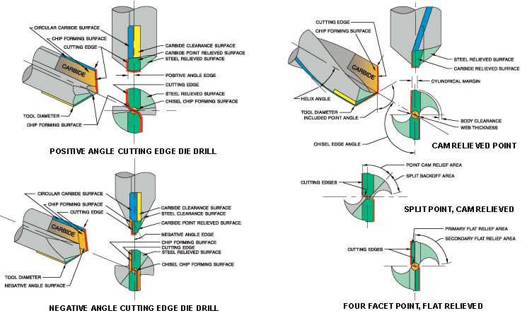
- More aggressive cutting edge geometries - shear, edge & rake angles
- A shattered solid carbide tool often damages the piece being machined
- Hardened tough alloy steel body provides superior structure to absorb shock loads
- Carbide cracks stopped in steel body pocket rather than shattering the entire tool
- Reduced scrap & machine downtime as even a cracked carbide tipped tool keeps cutting
- Carbide cracks stopped in steel body pocket rather than shattering the entire tool
ADVANTAGEs of CARBIDE TIPPED
VS.
CARBIDE INSERT
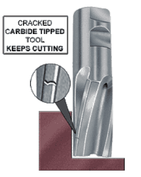 Cracked carbide tipped tool keeps cutting
 - Initial tooling costs far lower for carbide tipped tools
- Insert pocket interferes with chip flow
- Vibration-free brazed carbide tip permits higher feeds & speeds since inserts simply cannot be securely clamped to avoid all vibration problems
- Far better finish using carbide tipped tools
- Inserts are impractical for many operations such as reaming and most drilling
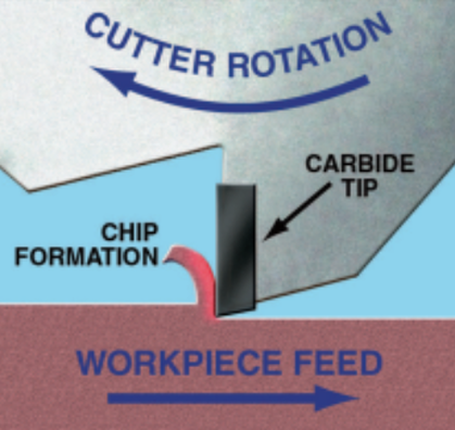
The Cutting Process
To understand the essence of carbide cutting tools, it's essential to comprehend the cutting process itself. At the heart of this process is an intense, concentrated force applied at the cutting edge, effectively separating the metal's individual crystals. This separation results in the creation of a continuous flowing chip, which eventually moves up the cutting tool face until internal stresses cause it to fracture, breaking away as a segmented or discontinuous chip.
During this process, a substantial amount of heat is generated at the cutting edge. This heat is primarily due to the friction between the tool and the workpiece as the chip is formed and flows along the cutting tool's face. Remarkably, individual carbide grains are so incredibly hard that they do not deform or flow under these intense forces and high temperatures, ensuring the tool's longevity and efficiency.
CARBIDE PRODUCTION
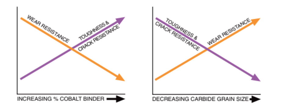
- Increasing % Cobalt Binder: The cobalt binder is a major factor in determining carbide's hardness and toughness. Increasing the cobalt content enhances the toughness, enabling the carbide to withstand mechanical shock or impact loads, which are typical during the cutting process.
- Decreasing Carbide Grain Size: Carbide grain size is another critical parameter. Smaller carbide grains contribute to a more wear-resistant cutting edge. It's a balance, as smaller grains can lead to decreased toughness.
Carbide Technical Specs
- Carbide Powder Creation: Metal powders, usually tungsten, and carbon, are heated to extremely high temperatures, exceeding 2800ºF. This process results in the creation of tungsten carbide powder grains that are exceptionally hard and stable at elevated temperatures.
- Powder Sorting and Mixing: The carbide powders are sorted by grain size and then recombined in appropriate ratios to achieve specific physical properties. Cobalt metal powders are mixed thoroughly with the tungsten powders.
- High-Pressure Compaction: The tungsten-carbide-cobalt mixture is forced under high pressure (30,000 psi) into molds of the desired shape and size. This forms the initial carbide blanks.
- Pre-Sintering: Carbide blanks undergo a low-temperature pre-sintering process, developing sufficient physical strength for handling.
- High-Temperature Sintering: Finally, the carbide blanks are sintered at temperatures ranging from 2500ºF to 2900ºF. This high-temperature sintering causes a dramatic shrinkage, almost 40% volume reduction, resulting in an extremely dense and hard material.
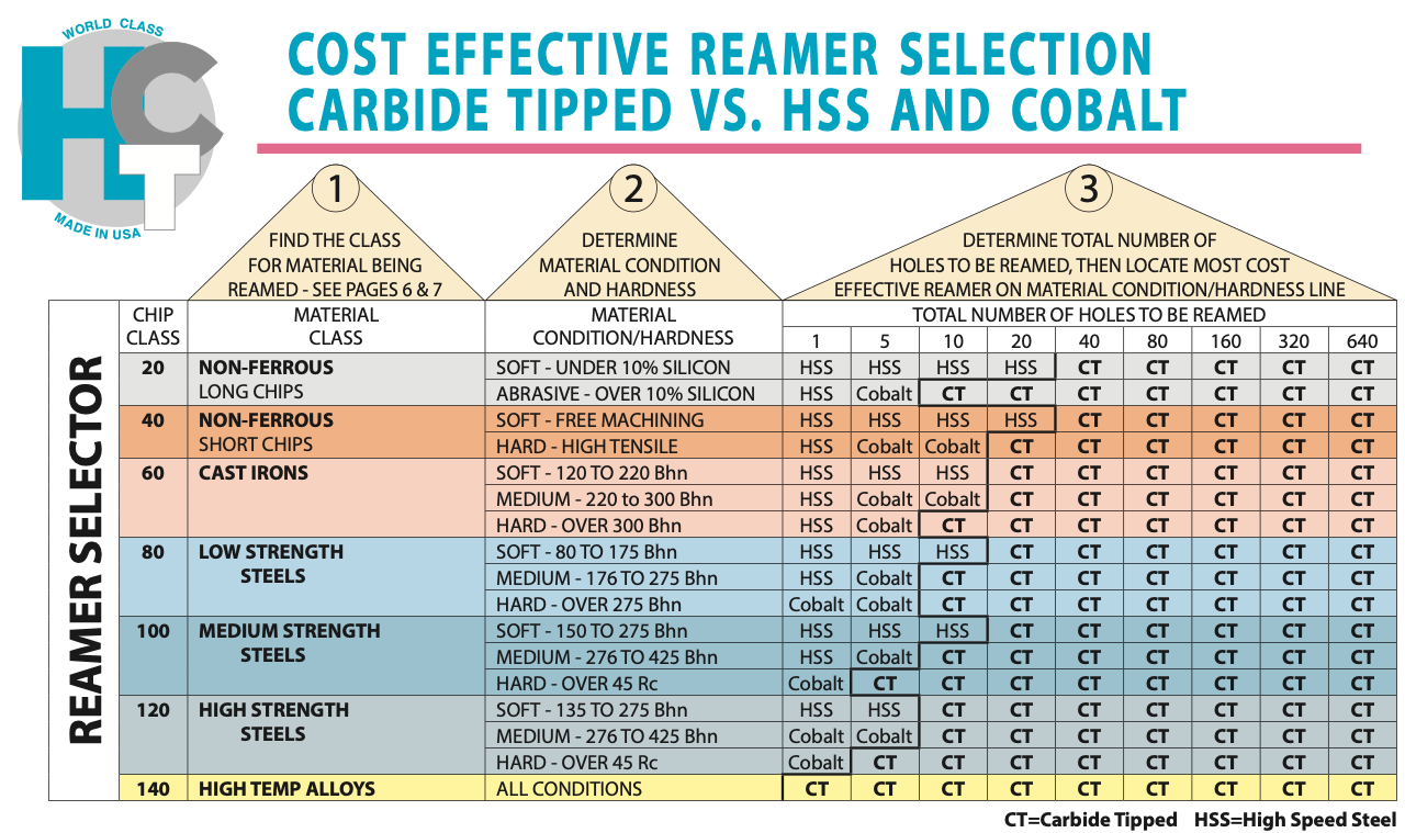
Here's the standard tolerances for the reamers.
Are you on our customer list yet?
Tool diameter tolerance
- Thru 11/2” tool diameter: plus .0003”, minus .0000”
- Over 11/2” tool diameter: plus .0004”, minus .0000”
- Thru 1/2” tool diameter: plus .0002”, minus .0000”
- Over 1/2” tool diameter thru 3/4”: plus .0003”, minus .0000”
- Over 3/4” tool diameter: plus .0004”, minus .0000”
Shank diameter tolerance
- minus .0005”, minus .0015”
- Thru 23/32” tool diameter: plus .0000”, minus .0010”
- Over 23/32” tool diameter: plus .0000”, minus .0015”
- Carbide tipped reamers are especially appropriate for close tolerance reaming. Because carbide is very highly resistant to wear, the reamer will produce accurate hole size and a smooth finish far longer than high speed steel or cobalt.
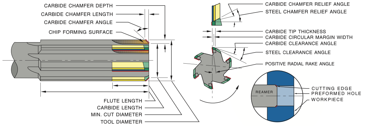
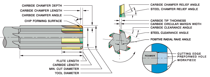
- The reamer is an end cutting tool, cutting only on the chamfer’s edge at the outside diameter of the preformed hole
- The standard 45° chamfer angle provides effective cutting action for most materials
Reamer Types
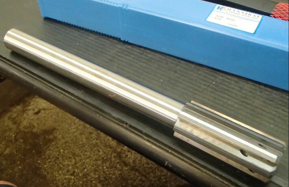
- General Purpose – Superior performance over high speed steel and cobalt; good in a wide variety of materials
- Material Specific – Excellent in large production runs due to material specific carbide & tool geometry
- Coolant Fed – Exceptional performance and tool life using material specific reamer technology and coolant fed capabilities; maximizes feeds & speeds
Reamer Specifications
- Geometry and carbide grade appropriate for material being machined
- Carbide tips brazed to tough hardened alloy steel body, except expansion reamers which are not hardened
- Polished flutes for easy chip flow
- ASME/ANSI B94.2; NAS 897; USCTI • Precision ground cutting edges• “Taper Shank No.” refers to American Standard taper series (formerly Morse taper series) per ASME/ANSI B5.10
- Material specific reamer shanks are ground to next smallest shank diameter listed in NAS 897 if tool diameter is within .005” of shank diameter
Carbide runs at higher Higher feeds & speeds due to heat resistant cutting edges and this reduces your machine cycle time per part. Carbide also provides consistent quality: It maintains hole size and surface finish far longer than steel. That is a direct result of longer tool life which reduces down time for tool changes. At the end of the run, your shop is more profitable using carbide tipper reamers from Hannibal Carbide.
Make sure you are using the correct flute style and tool type.
Stock Removal
HANNIBAL recommends 2-3% of the reamer diameter as a starting point for stock removal. 2% for steels and tough alloys, 3% for non-ferrous materials and cast irons. Solid carbide & carbide tipped reamers must have adequate stock to remove or they will rub in the hole and generate excessive heat, which leads to premature tool wear.
Improper Speeds & Feeds
The right combination of speeds and feeds is critical to tool life and consistent size and finish. Getting the correct starting points is a key element. Reaming is a finishing operation and proper speeds and feeds must be run to achieve size, straightness and finish.
Poor Fixturing
If the fixturing cannot hold the piece securely and in line with the spindle, then producing a good finish will be very difficult. A reamed hole is only going to be as good as the machine and fixturing used to machine and hold the part.
Excessing Runout (spindle or tool holder)
Runout leads to poor finishes, oversized, tapered, and bellmouth holes, as well as poor tool life. Floating holders or bushings can sometimes be used to compensate for runout, but the best solution is to fix the problem.
Improper Coolant
Make sure the coolant you are using is recommended for reaming your particular materials. Many coolants will prove effective for reaming if the concentration level is maintained with specifications. Take the time to check the levels on a regular basis.
Improper Sharpening or Geometry
If a new tool works fine, but fails to perform after resharpening, the problem is obvious. However, depending on the hardness and condition of the material you are reaming, the tool geometry may need to be altered to get optimum performance and tool life. Geometries most often changed are the circular margins, radial rake, and the primary chamfer clearance.
Material Changes (hardness and/or condition)
Castings lead the way in inconsistency. Hard spots, free carbides, and scale can all lead to inconsistent results when reaming. A heat treatment that varies just a few points from part to part can cause problems.
- It is very important to remember when optimizing your cycle that increasing feed will give you quicker cycles than running higher SFM at lower feed rates.
- With the surface feet per minute (SFM) at the manufacturers low range, begin trying to increase the feed rate. Increase in small increments, .001 - .0015 per revolution. Continue to increase the feed until an undesirable condition develops. This could be an unacceptable finish, a bell, tapered, or egg shaped hole, or poor size. At this point return to the previous feed rate. You are now at or close to the optimum feed rate.
- Increase the speed in increments of 10-20 SFM. Like the feed, increase until undesirable conditions appear, then return to the previous SFM. You should now be at or near the optimum speed and feed. It may also be necessary to fine-tune these numbers after a few runs to achieve the very best tool life.
As you seek the optimum speed and feed for your application, look and listen for signs or sounds that could save you time.
Listen for the reamer squealing upon entry—this means speed or feed is too high or alignment is poor.
Examine the chip for size and color. Examine the finish for signs of chatter.
Selecting the right tool, proper stock removal and correct speeds and feeds are all important and covered here in the Hannibal Carbide Reamer Guide.
"Ream it right the first time with Hannibal"
Flute Styles
Best suited for non-chip forming materials, i.e. cast iron, bronze and free cutting brass. Preferred hole condition would be a thru hole.
Designed to pull the chip out of the hole in a blind hole application.Due to aggressive flute geometry, a right hand spiral may cut slightly oversized.Effective in bridging interruptions, such as keyways, cross-holes, etc.Excellent in highly ductile materials.
Excellent in thru holes, as the flutes tend to push the chips out ahead of the reamer.Effective in bridging interruptions, such as keyways, cross-holes, etc.Good for reaming hard materials.Should provide the very best size and finish.
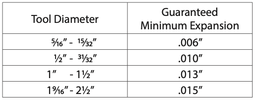
Designed for high production runs in abrasive materials, when size or finish can be rapidly lost.Expand the diameter by turning the screw clockwise.The tool is now ready to be reground back to its original diameter and resharpened.This process should produce like new tool performance.
Coolant Options
Center fed coolant design is used for blind hole reaming.Combine center fed coolant with right hand spiral for maximum chip clearing ability in highlyductile material.
Flute fed coolant design is used for thru hole reaming.Effective in a cavity large enough for chip clearance.Flute fed coolant will flush the chips ahead of the reamer, providing the best hole size and finish.
OPTIMUM OPERATING CONDITIONS
ABOUT
This is where we publish technical articles, applications stories, tip and tricks, new product announcements and press releases.
Archive
June 2024
May 2024
April 2024
March 2024
February 2024
January 2024
December 2023
November 2023
October 2023
September 2023
August 2023
July 2023
June 2023
May 2023
April 2023
March 2023
February 2023
January 2023
December 2022
November 2022
October 2022
September 2022
August 2022
July 2022
June 2022
May 2022
April 2022
March 2022
February 2022
January 2022
December 2021
November 2021
October 2021
September 2021
August 2021
July 2021
June 2021
May 2021
April 2021
March 2021
February 2021
January 2021
December 2020
November 2020
October 2020
September 2020
August 2020
July 2020
June 2020
May 2020
April 2020
March 2020
February 2020
January 2020
December 2019
November 2019
October 2019
September 2019
August 2019
July 2019
June 2019
May 2019
April 2019
March 2019
February 2019
January 2019
December 2018
November 2018
October 2018
September 2018
August 2018
July 2018
June 2018
May 2018
April 2018
March 2018
Categories
All
52/96 Workholding
Adhesive Workholding
Aerospace Manufacturing
Allen Benjamin
ATC Alignment
Better Edge
Blue Photon
Blue Photon Grip Pallet
Boring
Broaching
Brubaker Tool
BT Holders
Carbon Fiber
Case Study
CAT Holders
Chamfering
Coatings
Collet Nut
Collets
Collets: Lathe
Composite Machining
Coolant Lines
Countersink
Dataflute
Deburring
Decatur Diamond
Definitions
Diamond CVD
Diamond PCD
Dorian Tool
Drilling
Eastec
End MIll
EZ Burr
Face Milling
Fixturing
F&L Technical Sales
Fretting
Geometry
GMN Spindle
Graphite Machining
Grooving
Guide Bushings
GWS Tool Group
Hannibal Carbide
Heimatec
Henninger
Heritage Cutter
High Speed Whirling
Hirt-Line
Hommel + Keller
Horn Supermini
Horn USA
Hydraulic Toolholder
IMTS
Inserts
JET Whirling
Knurl Cutting
Knurl Cutting
Knurl Forming
Knurling
Live Tooling
Mate Workholding
Medical Device
Medical Manufacturing
MegaFORCE
Modern Industries
ModLOC
MPower
Nexturn Swiss
North American
Parlec
Part Marking
Platinum Tooling
Practical Machinist
Pull Studs
Reamers
Recondition
Retention Knobs
REV Broaching
RMT - Rocky Mountain Twist
Screw Threads
ShrinkLOCKED
Slot Cutting
Slot Milling
SpeedLOC
Spindle Repair
Spindle Speeder
Spindle Wear
Swiss
Taps
Taps: Bottom
Taps: HSSE
Taps: Plug
Taps: Roll Form
Taps: Taper
Techniks
Techniks SPINner
Technocrats
Tech Tip
Tecnicrafts
Threadmilling
Toolholders
Troubleshooting
Turbo-Whirling
Turret
USMTO
Weldon Tool
Workholding
Zero Point





 RSS Feed
