|
Getting a good understanding of the definitions of the parts of a tap will help you to better understand the functions of tap designs. Special thanks to Allen Benjamin for letting us share their short and simple explanations! 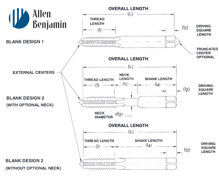 ALLOWANCE Minimum clearance between two mating parts; the prescribed variations from the basic size. ANGLE OF THREAD The angle included between the sides of the thread measured in an axial plane.AXISThe imaginary straight line that forms the longitudinal centerline of the tool or threaded part. BACK TAPER A gradual decrease in the diameter of the thread form on a tap from the chamfered end of the land towards the back which creates a slight radial relief in the threads. BASE OF THREAD The bottom section of the thread; the greatest section between the two adjacent roots. BASIC SIZE The theoretical or nominal standard size from which all variations are derived by application of allowances and tolerances. CHAMFER The tapering of the threads at the front end of each land of a tap by cutting away and relieving the crest of the first few teeth to distribute the cutting action over several teeth; Taper taps are chamfered 7-10 threads; plug tapsare chamfered 3-5 threads; semi-bottoming (or modified bottoming) taps are chamfered 2-2.5 threads; bottom-ing taps are chamfered 1-2 threads; taper pipe taps are chamfered 2-3.5 threads. 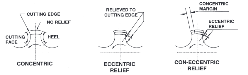 CHAMFER RELIEF The gradual decrease in land height from cutting edge to heel on the chamfered portion, to provide clearance for the cutting action as the tap advances. CREST The top surface joining the two sides or flanks of the thread; the crest of an external thread is at its major diameter, while the crest of an internal thread is at its minor diameter. CUTTING FACE The leading side of the land in the direction of cutting rotation on which the chip forms. FLUTE The longitudinal channels formed in a tap to create cutting edges on the thread profile, and to provide chip spaces and cutting fluid passages. HEEL The edge of the land opposite the cutting edge. HEIGHT OF THREAD The distance, measured radially, between the crest and the base of a thread. HELIX ANGLE The angle made by the advance of the thread as it wraps around an imaginary cylinder. HOOK The undercut on the face of the teeth. 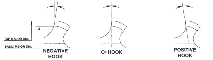 HOOK ANGLE The inclination of a concave cutting face, usually specified either as Chordal Hook or Tangential Hook.
INTERRUPTED THREAD TAP A tap having an odd number of lands with alternate teeth along the thread helix removed. In some cases alternate teeth are removed only for a portion of the thread length. LAND The part of the tap body which remains after the flutes are cut, and on which the threads are finally ground. The threaded section between the flutes of a tap. LEAD The axial distance a tap will advance along its axis in one revolution. On a single start, the lead and the pitch are identical; on a double start, the lead is twice the pitch. MAJOR DIAMETER Commonly known as the “outside diameter.” It is the largest diameter of the thread. MINOR DIAMETER Commonly known as the “root diameter.” It is the small-est diameter of the thread. PERCENT OF THREAD One-half the difference between the basic major diam-eter and the actual minor diameter of an internal thread, divided by the basic thread height, expressed as a percentage. 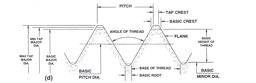 PITCH The distance from any point on a screw thread to a cor-responding point on the next thread, measured parallel to the axis and on the same side of the axis. The pitch equals one divided by the number of threads per inch. PITCH DIAMETER On a straight thread, the pitch diameter is the diameter of the imaginary co-axial cylinder...the surface of which would pass through the thread profiles at such points as to make the width of the groove equal to one-half of the basic pitch. On a perfect thread this occurs at the point where the widths of the thread and groove are equal. On a taper thread, the pitch diameter at a given position on the thread axis is the diameter of the pitch cone at that position. 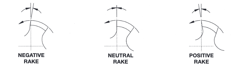 RAKE The angular relationship of the straight cutting face of a tooth with respect to a radial line through the crest of the tooth at the cutting edge.
RELIEF (or Thread Relief) The removal of metal from behind the cutting edge to provide clearance and reduce friction between the part being threaded and the threaded land. ROOT
The bottom surface joining the sides of two adjacent threads, and is identical with or immediately adjacent to the cylinder or cone from which the thread projects. SPIRAL FLUTE A flute with uniform axial lead in a spiral path around the axis of a tap. SPIRAL POINT The angular fluting in the cutting face of the land at the chamfered end; formed at an angle with respect to the tap axis of opposite hand to that of rotation. Its length is usually greater than the chamfer length and its angle with respect to the tap axis is usually made great enough to direct the chips ahead of the taps cutting action. STRAIGHT FLUTE A flute that forms a cutting edge lying in an axial plane. TOLERANCE In producing a tap to given specifications, tolerance is: (a.) the total permissible variation of a size; (b.) the differ-ence between the limits of size.
0 Comments
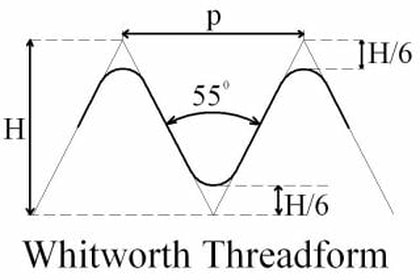
written and edited by Bernard Martin When discussing Screw Threads, it may be helpful to understand a little of the history behind them. 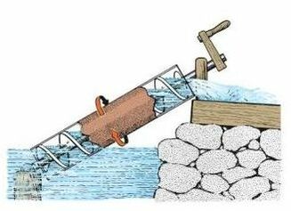 A Water Screw A Water Screw Let’s start with helical forms. Records dating to around 250 BC establish that it was Greek mathematician Archimedes who explained the mechanical principle of the screw as a form of wedge. He went on to formulate the mathematical characteristics of a helix. This was a precursor to the invention of the “water screw”, which provided a means to move water for irrigation, and as a method for ships to evacuate bilge water. It is apparent that other great civilizations contributed to the development and use of this tool, but the Greeks apparently had better people in the PR Department, as they get most of the historical credit. There is some evidence the water screw may have been used in Egypt before the time of Archimedes. The helical screw form was also used in presses by the Romans to make olive oil and wine, and later in printing presses like the first used by Gutenberg in the mid 1400’s. As time went on the screw-form used as a wedge became an alternative to bindings and rivets as fasteners. Even though it offered the advantage of faster assembly and disassembly, manufacturing methods were primitive. Mating threads were matched to each other by hand, one at a time. Not until the 17th Century, with the development of lathe technology, did manufacture of precision threads become possible. Even then, there were no standards for thread dimensions or form to assure performance and interchangeability of parts produced. Precision threads were being used in design of measuring instruments and manufacture of new technology. Railroads were being built and factories required new machines for mass production of goods. Increasing demand required a solution. Steps toward solving that problem would not come until the next century. Joseph Whitworth and William Sellers - Two to Lead the Way In 1841, a British engineer named Joseph Whitworth devised a set of standards for screw threads to address the need for uniformity and quality of performance in threaded parts. These standards prescribed a flank angle fixed at 55 degrees and standard thread pitches for given diameters.
In 1864, an American engineer named William Sellers presented another set of thread standards. Sellers proposed a 60-degree flank angle with flatted thread crests and roots. Like Whitworth’s standards, his proposal assigned standard thread pitches (threads per inch) for given diameters. The British standards were accepted worldwide, including the United States, but Sellers thread-form was easier to manufacture. Measurement was also simpler, as the form was based on the angles of an equilateral triangle. Some would argue the absence of radius on the thread crest and root left a weaker thread. Years of use would prove Seller’s thread-form more than adequate for the vast majority of applications. 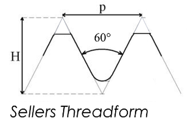 Even today, both of the thread-forms described above are in use. New standards have been assigned to address ever expanding uses. The addition of specialized forms like Acme, buttress, ballscrew, worm thread, and self-locking thread have been refined for function- specific use. There are threads for assembly of parts, fastening, creating motion, measurement devices, lifting, and fluid and gas sealing. The uses are almost endless.
There is a screwdriver in every house and business. Isn’t that a great indicator of the impact of screw threads on the world? Although most forms have been assigned standard specifications by governing bodies, there is no limit placed on the imaginations of engineers to fine-tune fit and function as well as to find new uses for the simple helical form developed centuries before. |
ABOUT
This is where we publish technical articles, applications stories, tip and tricks, new product announcements and press releases. Archive
June 2024
Categories
All
|
 RSS Feed
|
|
F&L Technical Sales Inc.
326 Woodland Way Russell, MA 01071 Established 1999
|
© 2024 F&L Technical Sales Inc.
All Rights Reserved site design: Rapid Production Marketing
|