|
The acquisition of North American Tool Corporation extends custom product capability into the threading space, a new offering for GWS that adds a powerful dimension to the already robust product and service portfolio. TAVARES, Fla., Feb. 4, 2020 /PRNewswire/ -- GWS Tool Group is pleased to announce it has acquired North American Tool Corporation (NATC).
"NATC is an exciting add for us," said Rick McIntyre, GWS' CEO. "Their customer service model is one of the best in the business, and their focus in taps and threadmills fits in like a perfect puzzle piece to our dynamic and holistic offering. We are very excited to be continually expanding our value proposition for our customers with highly additive acquisitions like this," McIntyre continued
"North American Tool is very excited to be joining GWS Tool Group, a company that embodies the attributes that have long made us successful," said Curt Lansbery, NATC President & CEO. "A customer-centric approach to business rooted in a commitment to quality and quick delivery marry perfectly with our model here at North American Tool. We have no doubt that this move to join GWS will be positive for our associates and will ensure the continued growth of the legacy that we have worked to develop." The team at NATC will continue to operate from the Illinois facility as a manufacturing arm of GWS Tool Group, and the company expresses intent toward continued investment in the facility, machinery and equipment, and human resources. Customers of NATC are said to expect continuity of the NATC offering and customer service disposition under cover of the GWS ownership. About GWS Tool Group GWS Tool Group is a U.S.-based, vertically integrated manufacturer of highly engineered custom, standard, and modified standard cutting tools, primarily servicing the aerospace and defense, power generation, automotive and medical sectors. GWS Tool Group has acquired multiple businesses in the course of its growth, which now serve as the respective manufacturing divisions of the Company.
0 Comments
1. BUILT TO LAST Designed to tap even the hardest materials, HSSE taps are made from high speed steel, which contains a higher concentration of cobalt and vanadium. This composition lends incredibly high resistance to wear, resulting in much longer average tool lives. Due to this, you can be confident that you’re purchasing a lasting, durable solution. 2. COLOR CODED When selecting taps, the number of available options can often be intimidating. To address this, Allen Benjamin color codes all of our products. With six color rings available, you — and your employees — will be able to easily locate the exact tap that they need, when they need it, thus reducing downtime, increasing efficiency, and preserving profits. 3. A TRUSTED SOURCE
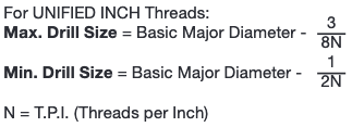
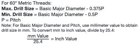
When you source from Allen Benjamin, you can rest easy knowing that you’re working with the industry’s most trusted supplier of HSSE and carbide taps. Just like F&L Technical Sales, Allen Benjamin is committed to treating our customers to a better experience, we focus on delivering high-quality products and — more importantly — attentive, knowledgeable customer service. Our F&L Technical Sales team will work with you to understand your application, recommend potential solutions, and supply you with the taps that you need. So, if you’ve been considering a new supplier for your operation’s carbide taps, HSSE taps, or smart tapping fluid, be sure to browse our website and contact us with any questions you have. Cold Forming Taps, also called Roll Taps, create threads by extruding the material in the drilled hole up into the thread form instead of removing material. This leads to a stronger thread because the material rearranges the material in the hole. Tap life is also increased because you are forming the thread instead of cutting the thread so there is nothing to wear out at the cutting edge. Roll Form Taps are en excellent choice for nickel based alloys that are prone to workhardening. The cold forming process causes the substrate material grain structure to be re-arranged and "squeezed" into the thread form. This cold working will increases the hardness of the substrate material. The following information is courtesy of Allen Benjamin . 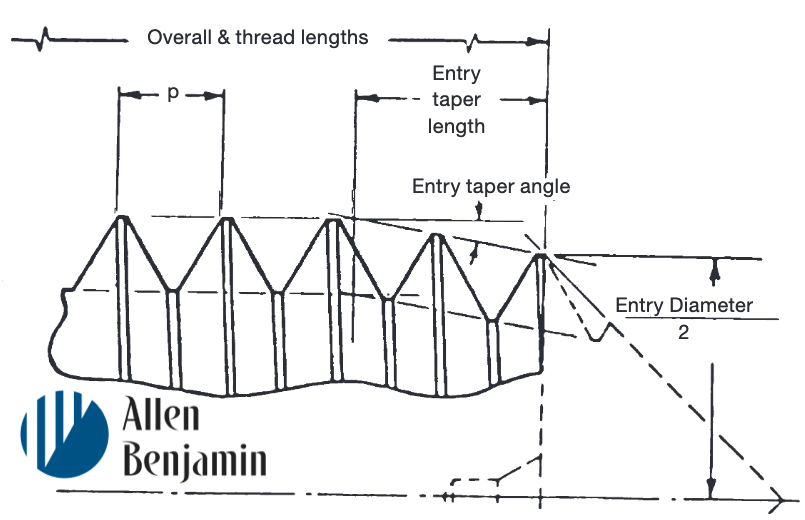 THREAD FORMING TAP ENTRY LENGTHS Entry taper length is measured on the full diameter of the thread forming lobes and is the axial distance from the entry diameter position to the theoretical intersection of tap major diameter and entry taper angle. Whenever entry taper length is specified in terms of number of threads, this length is measured in number of pitches (p). BOTTOMING LENGTH = 1-1/2 to 2-1/2 PITCHES PLUG LENGTH = 3 to 5 PITCHES The chamfer on BOTTOM style form taps is approximately 2 threads long and requires a drilled hole depth 3-4 pitches beyond the full thread required. When a controlled maximum chamfer shorter than 2 threads is required, an additional charge will apply. Allen Benjamin will not guarantee the performance of taps with the shorter chamfer. Entry diameter, measured at the thread crest nearest the front of the tap, is an appropriate amount smaller than the diameter of the hole drilled for tapping. See below for tap/drill size formulas, and formulas to determine maximum and minimum drill hole sizes for appropriate percent of thread. TAPPING SPEEDS Form taps operate most efficiently at spindle speeds 1-1/2 to 2 times faster than those recommended for conventional cutting taps, especially in softer materials and/or with fine pitch forming taps. LUBRICATION As higher speeds are attained, adequate lubrication is essential for prolonged tap life and thread quality. Since it is more important to ‘lubricate’ the cold-forming tap than to ‘cool’ the tap, these taps should be used with conventional lubricating cutting oils or EP (extreme pressure) rated oil...soluble oils and similar coolants are not recommended. PRE-TAPPED HOLE SIZE Forming taps require a LARGER pre-tapped hole size than conventional cutting taps. To insure a properly tapped (cold formed) hole, adhere to the following formulas below. FORMULA FOR TAP/DRILL SIZEs In both cases below, for inch and metric, use a whole number for % of thread. In the examples below you will see 65%, using 65, not .65. DECIMAL/INCH FORM TAPS  Here's an example: To determine drill size for a 1/4-20 thread forming tap at 65% of thread:  METRIC FORM TAPS  There is no true method of predicting percent of thread that will be obtained when tapping with forming taps due to the many variables involved. As a starting point, however, 55% for maximum drill size and 75% for minimum drill size can be used as a guide. Any desired percent of thread can be approximated by using drill sizes in between. To determine theoretical maximum and minimum drill sizes (for average operating conditions), see formulas below.
Here's a short guide on understanding Cut Tap Chamfers. This is an excerpt from Allen Benjamin's Technical Tap Guide Engineering Data. 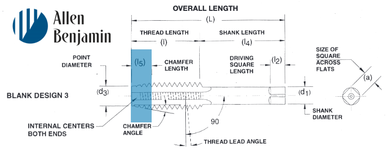 A tap chamfer is the tapering of the threads to distribute cutting action over several teeth. The type of hole to be tapped has much to do with the chamfer style of that tap that’s best suited. Some holes go all the way through. Some, while not through-holes, are relatively deep. Some are quite shallow (a little deeper than diameter). Each of these three kinds of holes - through, deep-bottoming blind, and shallow bottoming - has a tap chamfer best suited to specific threading requirements. 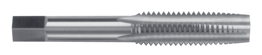 Allen Benjamin Taper Tap Taper Taps This style, with a 7-10 thread chamfer, has the longest chamfer of the three to distribute action over the maximum number of teeth; and the taper also acts as a guide in starting the cutting action in the hole. Taper style taps start the thread square with the workpiece. Taper taps are commonly used in through holes and in materials where a tapered guide is necessary. 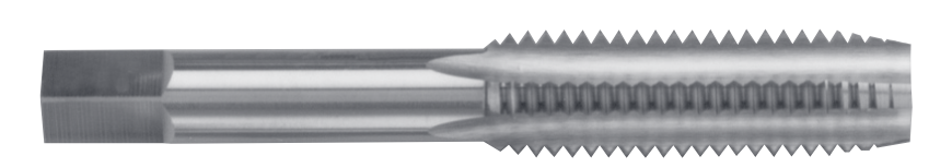 Allen Benjamin Plug Tap Plug Taps This style, with a 3-5 thread chamfer, is most widely used in through holes and where there is sufficient room at the bottom in blind holes. Semi (or Modified) Bottoming Taps This style, with a 2 to 2.5 thread chamfer, should be used when-ever possible in difficult material applications in blind holes, when threads are not required to the bottom of the hole 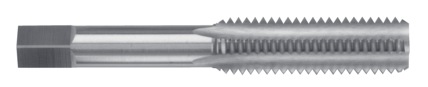 Allen Benjamin Bottoming Tap Bottoming Style This style, designed with a 1 to 2 thread chamfer, is made with just enough chamfer for starting in the hole; as the name implies, it is designed to thread blind holes to the bottom. PLEASE NOTE: Taper, plug and bottoming taps as a set, in a given size (for example: 1/4-20 NC) are identical as to size, length and vi-tal measurements; the difference is in the chamfered threaded portion at the point. As a rule, such taps when used by hand are furnished in sets of three of a given size...namely, taper, plug and bottoming (and should be used in that order)
Getting a good understanding of the definitions of the parts of a tap will help you to better understand the functions of tap designs. Special thanks to Allen Benjamin for letting us share their short and simple explanations! 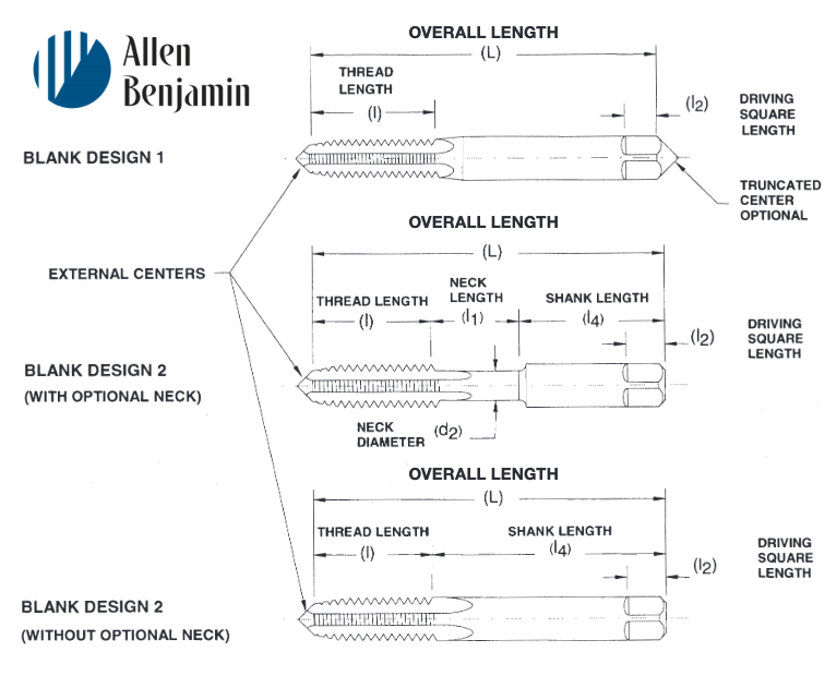 ALLOWANCE Minimum clearance between two mating parts; the prescribed variations from the basic size. ANGLE OF THREAD The angle included between the sides of the thread measured in an axial plane.AXISThe imaginary straight line that forms the longitudinal centerline of the tool or threaded part. BACK TAPER A gradual decrease in the diameter of the thread form on a tap from the chamfered end of the land towards the back which creates a slight radial relief in the threads. BASE OF THREAD The bottom section of the thread; the greatest section between the two adjacent roots. BASIC SIZE The theoretical or nominal standard size from which all variations are derived by application of allowances and tolerances. CHAMFER The tapering of the threads at the front end of each land of a tap by cutting away and relieving the crest of the first few teeth to distribute the cutting action over several teeth; Taper taps are chamfered 7-10 threads; plug tapsare chamfered 3-5 threads; semi-bottoming (or modified bottoming) taps are chamfered 2-2.5 threads; bottom-ing taps are chamfered 1-2 threads; taper pipe taps are chamfered 2-3.5 threads. 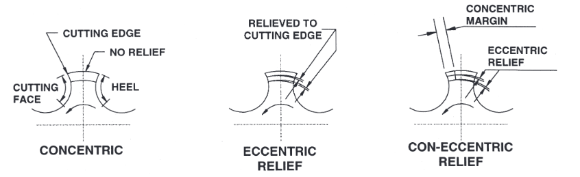 CHAMFER RELIEF The gradual decrease in land height from cutting edge to heel on the chamfered portion, to provide clearance for the cutting action as the tap advances. CREST The top surface joining the two sides or flanks of the thread; the crest of an external thread is at its major diameter, while the crest of an internal thread is at its minor diameter. CUTTING FACE The leading side of the land in the direction of cutting rotation on which the chip forms. FLUTE The longitudinal channels formed in a tap to create cutting edges on the thread profile, and to provide chip spaces and cutting fluid passages. HEEL The edge of the land opposite the cutting edge. HEIGHT OF THREAD The distance, measured radially, between the crest and the base of a thread. HELIX ANGLE The angle made by the advance of the thread as it wraps around an imaginary cylinder. HOOK The undercut on the face of the teeth. 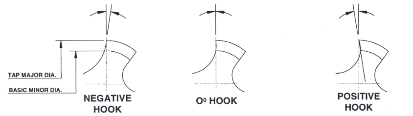 HOOK ANGLE The inclination of a concave cutting face, usually specified either as Chordal Hook or Tangential Hook.
INTERRUPTED THREAD TAP A tap having an odd number of lands with alternate teeth along the thread helix removed. In some cases alternate teeth are removed only for a portion of the thread length. LAND The part of the tap body which remains after the flutes are cut, and on which the threads are finally ground. The threaded section between the flutes of a tap. LEAD The axial distance a tap will advance along its axis in one revolution. On a single start, the lead and the pitch are identical; on a double start, the lead is twice the pitch. MAJOR DIAMETER Commonly known as the “outside diameter.” It is the largest diameter of the thread. MINOR DIAMETER Commonly known as the “root diameter.” It is the small-est diameter of the thread. PERCENT OF THREAD One-half the difference between the basic major diam-eter and the actual minor diameter of an internal thread, divided by the basic thread height, expressed as a percentage. 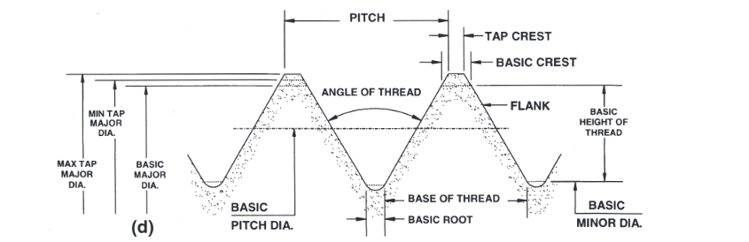 PITCH The distance from any point on a screw thread to a cor-responding point on the next thread, measured parallel to the axis and on the same side of the axis. The pitch equals one divided by the number of threads per inch. PITCH DIAMETER On a straight thread, the pitch diameter is the diameter of the imaginary co-axial cylinder...the surface of which would pass through the thread profiles at such points as to make the width of the groove equal to one-half of the basic pitch. On a perfect thread this occurs at the point where the widths of the thread and groove are equal. On a taper thread, the pitch diameter at a given position on the thread axis is the diameter of the pitch cone at that position. 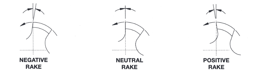 RAKE The angular relationship of the straight cutting face of a tooth with respect to a radial line through the crest of the tooth at the cutting edge.
RELIEF (or Thread Relief) The removal of metal from behind the cutting edge to provide clearance and reduce friction between the part being threaded and the threaded land. ROOT
The bottom surface joining the sides of two adjacent threads, and is identical with or immediately adjacent to the cylinder or cone from which the thread projects. SPIRAL FLUTE A flute with uniform axial lead in a spiral path around the axis of a tap. SPIRAL POINT The angular fluting in the cutting face of the land at the chamfered end; formed at an angle with respect to the tap axis of opposite hand to that of rotation. Its length is usually greater than the chamfer length and its angle with respect to the tap axis is usually made great enough to direct the chips ahead of the taps cutting action. STRAIGHT FLUTE A flute that forms a cutting edge lying in an axial plane. TOLERANCE In producing a tap to given specifications, tolerance is: (a.) the total permissible variation of a size; (b.) the differ-ence between the limits of size. |
ABOUT
This is where we publish technical articles, applications stories, tip and tricks, new product announcements and press releases. Archive
March 2024
Categories
All
|

 RSS Feed
|
|
F&L Technical Sales Inc.
326 Woodland Way Russell, MA 01071 Established 1999
|
© 2024 F&L Technical Sales Inc.
All Rights Reserved site design: Rapid Production Marketing
|