|
Dorian Tool has some very detailed technical information in their Solution Tool catalog to address deep hole boring. First we're going to list the fundamental rules of selecting the correct boring bar and then take a deeper dive into the fundamentals of troubleshooting. If you want more information, technical specifications and much more detailed information on troubleshooting you can download the Solution Tool catalog below. 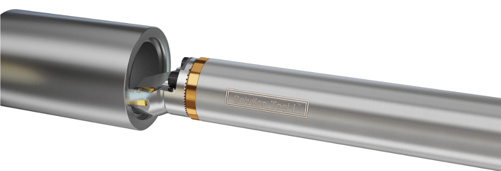 DEEP HOLE BORING |

| Excessive and inconsistent run-out from a properly setup ER collet chuck assembly typically occurs due to friction build-up between the 30° face of the collet and the collet nut. As the collet nut presses down and turns against the 30° face of the collet, the collet face will tend to twist with the collet nut, distorting the shape of the collet. This radial distortion negatively affects tool run-out sine the collet bore is not longer straight. Techniks', Mike Eneix took an uncoated, imported nut and put it to the test against the PowerCOAT nut. They took them to the limit to see which one gives you more holding power. Check out the video test below! | 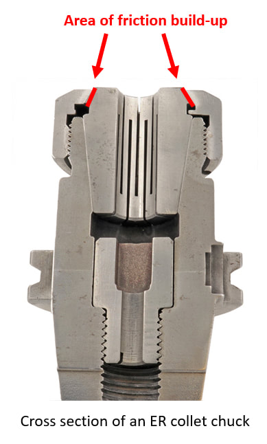 |
HORN’s new high performance coatings IG6 and SG3 are a testaments to engineering expertise in tool manufacturing.
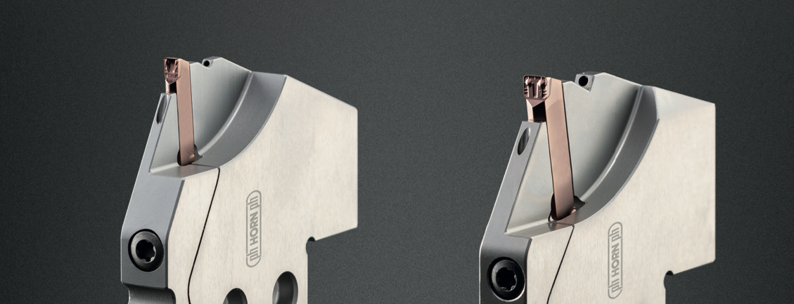
Horn USA Carbide Grade IG6: More performance in the machining of steel and stainless steels.
The new coatings are less than 0.005 mm (.0002”) thick and an essential part of modern tool technology. Testing has shown that the new tool coatings extend the service life of carbide tools by over one-thousand percent.
IG6 is a copper colored aluminum-titanium-silica nitride (AlSiTiN) coating designed for use in machining materials P and M with grooving inserts type S224 and S229. In conjunction with the carbide substrate, the coating allows for faster material removal rates and significantly extended wear resistance in machining materials P and M. Standard inserts are available from stock.
IG6 is a copper colored aluminum-titanium-silica nitride (AlSiTiN) coating designed for use in machining materials P and M with grooving inserts type S224 and S229. In conjunction with the carbide substrate, the coating allows for faster material removal rates and significantly extended wear resistance in machining materials P and M. Standard inserts are available from stock.
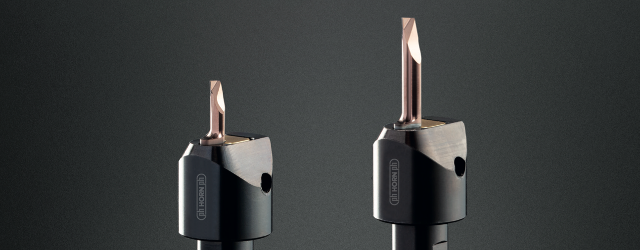
Horn USA Carbide Grade SG3. The choice for machining hardened steel and difficult-to-machine materials.
SG3 is designed for use in titanium and super-alloys as well as turning and grooving applications in hardened materials, up to 58 HRC. The coating can be function in temperatures up to 1,100 degrees Celsus (2,012 degrees Fahrenheit).
HORN designed this coating to deliver outstanding performance with materials that are difficult to machine. The advantage of the tool coating have been proven on selected tool systems from HORN.
The Supermini® system 105 with SG3 coating is available from stock. In both cases, the IG6 and SG3 coatings are applied in-house, allowing for reduced delivery time.
HORN has developed a high level of expertise in coating precision tools since it began in-house coating processes. From five employees in the beginning to more than fifty employees, the aim has always been to create and invest in modern coating technologies for precision cutting tools.
The HORN team was the first in the world to take delivery of HiPIMS systems from CemeCon. The opportunities to develop hard and tough coating with a homogeneous structure has provided this team the flexibility to create advancements that benefit customers who demand precision tools in demanding applications.
The HORN team was the first in the world to take delivery of HiPIMS systems from CemeCon. The opportunities to develop hard and tough coating with a homogeneous structure has provided this team the flexibility to create advancements that benefit customers who demand precision tools in demanding applications.
Check out the video clip about Blue Photon using ultraviolet light to cure BlueGrip workholding adhesive on the grippers!
| In this month’s Swarf Talk they deep dive into how you can reduce set-up times, increase spindle uptime, increase speeds and feeds, increase tool life longevity, improve surface finish, eliminate vibration, utilize your machine envelope and ultimately make more money by maximizing your efficiencies on your milling machines simply with workholding solutions and innovations! | 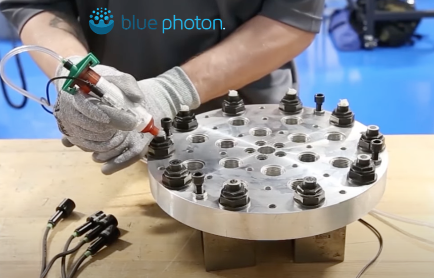 |
Watch the full episode covering workholding on Swarf Talk HERE
Swarf and Chips is sponsored by Intoco Special Steels and Alloys.
Courtesy of MTD CNC Media and Swarf and Chips.
Ian Sandusky from Practical Machinist takes a tour of GWS Tool Group's EASTEC Trade Show booth with John Kiffner from, showcasing their line of cutting tools.
Ian dices into the monoblocks, diamond-style milling tools, GWS' ceramics and custom thread whirling inserts and last, but not least, their Hurrimill AT4 end mill tool and the Alumigator ASR5 end mill tool.
Have any questions? Drop them in the comments!
Ian dices into the monoblocks, diamond-style milling tools, GWS' ceramics and custom thread whirling inserts and last, but not least, their Hurrimill AT4 end mill tool and the Alumigator ASR5 end mill tool.
Have any questions? Drop them in the comments!
We've been asked by one of our customers recently to post the standard reamer tolerances for Hannibal Carbide Reamers.
Here's the standard tolerances for the reamers.
Are you on our customer list yet?
Here's the standard tolerances for the reamers.
Are you on our customer list yet?

Tool diameter tolerance
General Purpose & Coolant Fed Reamers
- Thru 11/2” tool diameter: plus .0003”, minus .0000”
- Over 11/2” tool diameter: plus .0004”, minus .0000”
- Thru 1/2” tool diameter: plus .0002”, minus .0000”
- Over 1/2” tool diameter thru 3/4”: plus .0003”, minus .0000”
- Over 3/4” tool diameter: plus .0004”, minus .0000”
Shank diameter tolerance
General purpose
- minus .0005”, minus .0015”
- Thru 23/32” tool diameter: plus .0000”, minus .0010”
- Over 23/32” tool diameter: plus .0000”, minus .0015”
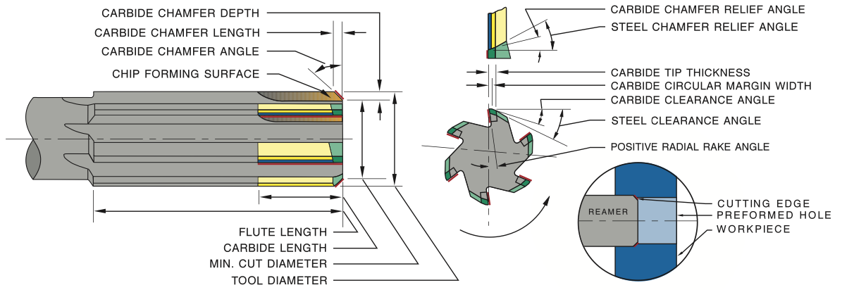
The reamer is used to finish machine a previously formed hole to an exact diameter with a smooth finish. It should not be used to significantly enlarge a hole (max. 5% – depending on material and hardness).
- Carbide tipped reamers are especially appropriate for close tolerance reaming. Because carbide is very highly resistant to wear, the reamer will produce accurate hole size and a smooth finish far longer than high speed steel or cobalt.
- The reamer is an end cutting tool, cutting only on the chamfer’s edge at the outside diameter of the preformed hole
- The standard 45° chamfer angle provides effective cutting action for most materials
Reamer Types
- General Purpose – Superior performance over high speed steel and cobalt; good in a wide variety of materials
- Material Specific – Excellent in large production runs due to material specific carbide & tool geometry
- Coolant Fed – Exceptional performance and tool life using material specific reamer technology and coolant fed capabilities; maximizes feeds & speeds
Reamer Specifications
- Geometry and carbide grade appropriate for material being machined
- Carbide tips brazed to tough hardened alloy steel body, except expansion reamers which are not hardened
- Polished flutes for easy chip flow
- ASME/ANSI B94.2; NAS 897; USCTI • Precision ground cutting edges• “Taper Shank No.” refers to American Standard taper series (formerly Morse taper series) per ASME/ANSI B5.10
- Material specific reamer shanks are ground to next smallest shank diameter listed in NAS 897 if tool diameter is within .005” of shank diameter
| Expansion reamers can be expanded for regrinding as shown in this chart. | 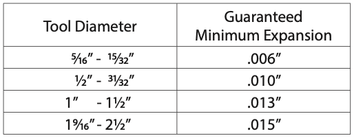 |

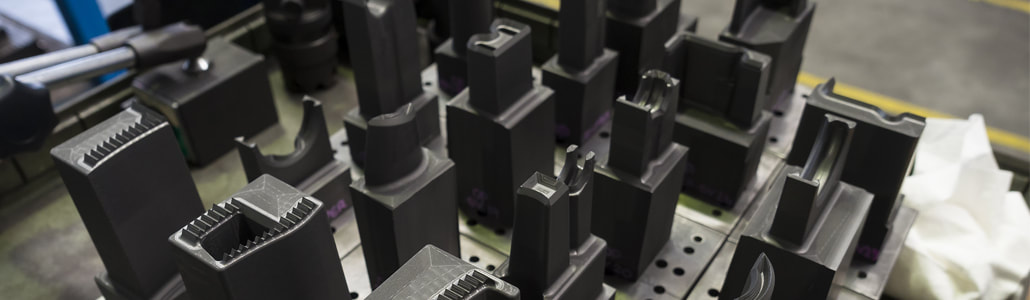
Decatur Diamond has a complete line of precision cutting tools specifically designed for machining graphite. The tool geometries are optimized for such applications as electrodes, molds, and hydrogen fuel cells. These designs provide excellent cutting performance while not sacrificing tool life. Fewer changeovers and more time in the cut promote long runs and application automation for improved cost savings.
CVD coated diamond tools are a perfect match for machining the graphite moldforms for EDM. The abrasive nature of EDM graphite grades severely limit the life of carbide tools, and PCD diamond tools are not available in the configurations required for detailed moldmaking.
Tools with diamond on the surface wear longer and have a lower coefficient of friction. These characteristics provide substantial benefit to machining operations.
Because diamond tools last 10 to 50 times longer than carbide tools, they:
When cutting graphite, most tool wear is caused by the abrasive nature of the graphite structure rather than by the material temperature or cutting speed. Unlike metal cutting, there is no heat generated when machining graphite, so tool speed is typically not seen as a wear factor. This distinction warrants the need for an abrasion resistant tool surface such as CVD diamond.
Because small feeds and depths of cut do not lead to increasing the amount of material chipping, tool wear will advance rapidly with light feed, but stabilize as feed is increased. Therefore, in addition to increasing the volume of material removed, increasing feed can extend tool life.
The depth of cut should not exceed one-half of an insert’s leg length or one-third of an endmill’s diameter. These parameters will minimize breakage at the exit of a cut.
Tool life is determined by the quality of the cutting edge and the thickness of the diamond layer at the cutting edge. A tool will go through a break in period that refines the cutting edge, resulting in an improved surface finish. This will be followed by a prolonged period of consistent performance and a gradual wearing of the diamond layer. End-of-life occurs when the diamond wears through, revealing the carbide substrate or when the diamond surface becomes chipped or fractured.
Tools with diamond on the surface wear longer and have a lower coefficient of friction. These characteristics provide substantial benefit to machining operations.
Because diamond tools last 10 to 50 times longer than carbide tools, they:
- Improve dimensional accuracy and consistency of machined parts
- Greatly reduce number of tool changes, increasing productivity
- Increase machine utilization
- Allow for unattended machine operations
- Quickly pay for themselves
When cutting graphite, most tool wear is caused by the abrasive nature of the graphite structure rather than by the material temperature or cutting speed. Unlike metal cutting, there is no heat generated when machining graphite, so tool speed is typically not seen as a wear factor. This distinction warrants the need for an abrasion resistant tool surface such as CVD diamond.
Because small feeds and depths of cut do not lead to increasing the amount of material chipping, tool wear will advance rapidly with light feed, but stabilize as feed is increased. Therefore, in addition to increasing the volume of material removed, increasing feed can extend tool life.
The depth of cut should not exceed one-half of an insert’s leg length or one-third of an endmill’s diameter. These parameters will minimize breakage at the exit of a cut.
Tool life is determined by the quality of the cutting edge and the thickness of the diamond layer at the cutting edge. A tool will go through a break in period that refines the cutting edge, resulting in an improved surface finish. This will be followed by a prolonged period of consistent performance and a gradual wearing of the diamond layer. End-of-life occurs when the diamond wears through, revealing the carbide substrate or when the diamond surface becomes chipped or fractured.
Endmilling
Tool configuration: use square endmills with a small radius whenever possible. Diamond tools are more brittle than carbide tools and sharp corners may break upon entry into a cut at high feed rates. A radius of 0.010” to 0.015” will greatly strengthen the tool, providing extra durability.
For roughing at high feed rates 2-flute endmills should be used to minimize the possibility of tool breakage from flute packing. For general purpose and finish cutting use 4 flutes. Improved surface finish and longer life usually result from multiple flutes in finishing operations.
Chipping: to avoid chipping, several techniques can be employed. Milling a short distance at the exit side of the part before starting the cut is very effective in avoiding breakout, just as chamfering the end of a cylinder is for turning. Lowering feed rates will lessen chipping upon exit, but directly affects productivity. Tool rotation can be used to lessen exit edge chipping for flat surfaces by using climb milling rotation rather than conventional milling rotation.
Feed rate: it is important to keep the tool engaged in the cut. If the feed rates drop too low (<.0001 to .0005” or <.00025 to .013mm) the tool tends to burnish the part, rather than cut. This can cause rapid tool wear.
When calculating the correct RPM for chip load at a given traverse speed it is important to consider if the machine is ever reaching the optimum traverse speed. It can take 1⁄2” or more to reach a high traverse speed. If the tool path has a lot of small adjustments, reduce RPM’s as the tool is never reaching the full traverse speed.
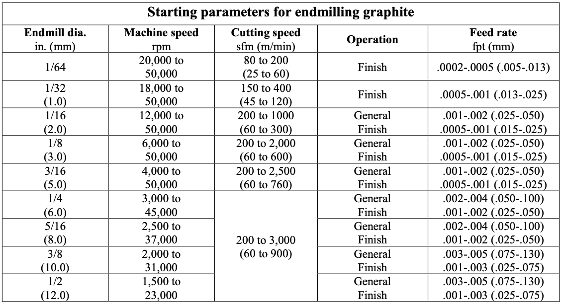
Machining Parameters: starting conditions vary considerably; 2000 SFM and 0.004” per flute per revolution is a conservative start point for 1⁄4” and larger endmills.
Feed rate: it is important to keep the tool engaged in the cut. If the feed rates drop too low (<.0001 to .0005” or <.00025 to .013mm) the tool tends to burnish the part, rather than cut. This can cause rapid tool wear.
When calculating the correct RPM for chip load at a given traverse speed it is important to consider if the machine is ever reaching the optimum traverse speed. It can take 1⁄2” or more to reach a high traverse speed. If the tool path has a lot of small adjustments, reduce RPM’s as the tool is never reaching the full traverse speed.
Machining Parameters: starting conditions vary considerably; 2000 SFM and 0.004” per flute per revolution is a conservative start point for 1⁄4” and larger endmills.
Drilling
Dust removal: particular care should be used to clear the machining dust from holes during drilling. Proper removal will allow using higher spindle speed as well as reducing drill wear.
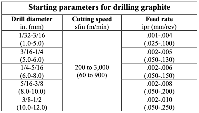
Machining Parameters: the table below shows starting machining parameters for drilling graphite. As are all applications, these conditions will vary according to the grade of the graphite being machined and the set-up and dust removal practices.
Dust removal: particular care should be used to clear the machining dust from holes during drilling. Proper removal will allow using higher spindle speed as well as reducing drill wear.
Machining Parameters: the table below shows starting machining parameters for drilling graphite. As are all applications, these conditions will vary according to the grade of the graphite being machined and the set-up and dust removal practices.
Profiling
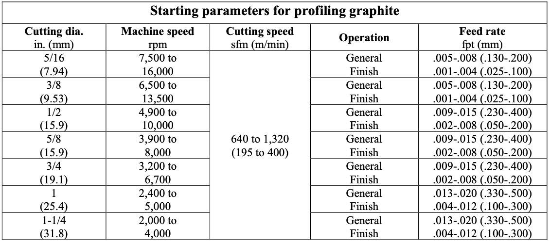
Machining Parameters: the table below shows starting machining parameters for Dapra & Millstar style ball nose, flat bottom, and back draft profiling cutters.
Machining Parameters: the table below shows starting machining parameters for Dapra & Millstar style ball nose, flat bottom, and back draft profiling cutters.
Turning and milling with inserted cutters
Tool configuration: perishable inserts with 1/64” to 1/32” nose radii are most effectively used for turning and milling graphite. A positive rake insert with a finish ground flank is preferred.
Surface finish: finish can be improved be selecting the appropriate tool geometry and feed rates. Larger nose radii will improve finish, but with increased tool pressure. A smaller nose radius will relieve pressure, but feed must be reduced to achieve comparable surface finish. DOC will not affect surface finish unless it causes excess tool pressure resulting in vibration, or if it is too light (under 0.005”) to remove an adequate amount of material.
Breakout: breakout at the end of a pass is always a concern. This can be avoided by having a chamfer cut on the end of the part to ease exit of the tool or provide stock which can be later cut off. Avoid square-nosed cut-off tools to prevent breaking prior to completion of the cut. A 20- degree angle is recommended.
Turning
Workpiece configuration: when machining long rods and cylinders, higher speeds and depths of cut can be employed with higher strength graphite materials.
Depth of cut: DOC should always be maximized when possible without incurring distortion of the part. When distortion is present, feed and DOC must be adjusted. Lower feed rates will allow holding deeper cuts. Feed rates of 0.005” per revolution for roughing and between 0.001” to 0.003”: for finishing might be necessary. Deeper cuts always generate higher pressures and larger fracturing particles, thereby producing rougher surface finishes.
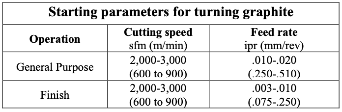
Machining Parameters: the table below shows starting machining parameters for general purpose and finish turning.
Workpiece configuration: when machining long rods and cylinders, higher speeds and depths of cut can be employed with higher strength graphite materials.
Depth of cut: DOC should always be maximized when possible without incurring distortion of the part. When distortion is present, feed and DOC must be adjusted. Lower feed rates will allow holding deeper cuts. Feed rates of 0.005” per revolution for roughing and between 0.001” to 0.003”: for finishing might be necessary. Deeper cuts always generate higher pressures and larger fracturing particles, thereby producing rougher surface finishes.
Machining Parameters: the table below shows starting machining parameters for general purpose and finish turning.
Milling
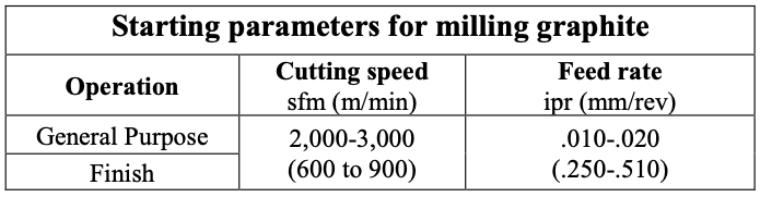
Workpiece configuration: when milling large surfaces or volumes, higher speeds and depths of cut can be employed. Use higher strength graphite materials when there are thin walls involved.
Depth of cut: DOC should always be maximized when possible, to reduce multiple passes. Lower feed rates will allow holding deeper cuts. Feed rates of 0.004”/tooth/revolution for roughing and between 0.0005” to 0.002”/tooth/revolution for finishing might be necessary.
Multiple cutters: for multiple-pocket milling cutters it is recommended that axial alignment be used to align all inserts within +/-0.0002” for best results. This will improve surface finish and reduce insert wear, as all the inserts will be cutting equally.
Machining Parameters: the table below shows starting machining parameters for general purpose and finish turning.
ABOUT
This is where we publish technical articles, applications stories, tip and tricks, new product announcements and press releases.
Archive
May 2024
April 2024
March 2024
February 2024
January 2024
December 2023
November 2023
October 2023
September 2023
August 2023
July 2023
June 2023
May 2023
April 2023
March 2023
February 2023
January 2023
December 2022
November 2022
October 2022
September 2022
August 2022
July 2022
June 2022
May 2022
April 2022
March 2022
February 2022
January 2022
December 2021
November 2021
October 2021
September 2021
August 2021
July 2021
June 2021
May 2021
April 2021
March 2021
February 2021
January 2021
December 2020
November 2020
October 2020
September 2020
August 2020
July 2020
June 2020
May 2020
April 2020
March 2020
February 2020
January 2020
December 2019
November 2019
October 2019
September 2019
August 2019
July 2019
June 2019
May 2019
April 2019
March 2019
February 2019
January 2019
December 2018
November 2018
October 2018
September 2018
August 2018
July 2018
June 2018
May 2018
April 2018
March 2018
Categories
All
52/96 Workholding
Adhesive Workholding
Aerospace Manufacturing
Allen Benjamin
ATC Alignment
Better Edge
Blue Photon
Blue Photon Grip Pallet
Boring
Broaching
Brubaker Tool
BT Holders
Carbon Fiber
Case Study
CAT Holders
Chamfering
Coatings
Collet Nut
Collets
Composite Machining
Countersink
Dataflute
Deburring
Decatur Diamond
Definitions
Diamond CVD
Diamond PCD
Dorian Tool
Drilling
Eastec
End MIll
EZ Burr
Face Milling
Fixturing
Fretting
Geometry
GMN Spindle
Graphite Machining
Grooving
GWS Tool Group
Hannibal Carbide
Heimatec
Henninger
Heritage Cutter
High Speed Whirling
Hommel + Keller
Horn Supermini
Horn USA
Hydraulic Toolholder
IMTS
Inserts
JET Whirling
Knurl Cutting
Knurl Cutting
Knurl Forming
Knurling
Live Tooling
Mate Workholding
Medical Device
Medical Manufacturing
MegaFORCE
Modern Industries
ModLOC
MPower
Nexturn Swiss
North American
Parlec
Part Marking
Platinum Tooling
Practical Machinist
Pull Studs
Reamers
Recondition
Retention Knobs
REV Broaching
RMT - Rocky Mountain Twist
Screw Threads
ShrinkLOCKED
Slot Cutting
Slot Milling
SpeedLOC
Spindle Repair
Spindle Speeder
Spindle Wear
Swiss
Taps
Taps: Bottom
Taps: HSSE
Taps: Plug
Taps: Roll Form
Taps: Taper
Techniks
Techniks SPINner
Tech Tip
Tecnicrafts
Threadmilling
Toolholders
Troubleshooting
Turbo-Whirling
Turret
USMTO
Weldon Tool
Workholding
Zero Point
 RSS Feed